How to Route Cables Under a Desk
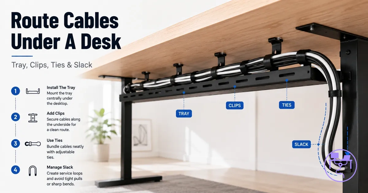
Under-desk cable routing starts with creating a supported cable path that keeps cables accessible and allows appropriate cable slack for the desk setup. A desk cable management system can work more effectively when each cable run follows a planned route instead of crossing randomly. The core routing principle is to support cables along a defined path on the desk underside.
Under-desk cable routing is the process of guiding power, data, and peripheral cables through a structured path beneath a desk using support components such as a cable tray, cable clips, or a cable sleeve. Within a desk cable management system, the goal is to balance cable support, access, and future adjustments rather than simply moving cables out of sight. Cable paths should remain reachable when equipment changes or maintenance is needed. For a broader overview of the system context, see the desk cable management system hub.
Tangled cables, dangling cables, and loose cables often develop when a cable path is not planned before cables are secured. A route that separates cable groups, preserves cable slack, and supports the cable run along the desk underside can reduce correction work later. Power cable placement may require a different routing path from data or peripheral cables when access or maintenance needs differ. Understanding these routing variables prepares the foundation for the routing basics that follow.
If the setup includes monitor cables, a floor-to-desk power cable, or a fixed desk with limited underside space, the routing path may need adjustment. Cable tray placement, cable clips, and cable sleeve positioning can vary based on cable load, device location, and power access points. The routing objective remains the same: keep cables supported, accessible, and not over-tightened while following a clear cable path.
Under-Desk Cable Routing Basics
Under-desk cable routing is the process of guiding a cable run from device points along a defined cable path on the desk underside while maintaining support, access, and slack. The purpose is to create a route that remains organized, reachable, and adaptable as equipment or cable needs change. Cable path, support, access, and slack are the basic variables that determine how under-desk cable routing works.
Under-Desk Cable Routing Basics are easier to understand when the cable path is viewed as a route that moves cables from device points to the desk underside. The diagram below clarifies how the cable run travels through support points while preserving access and a controlled slack area.
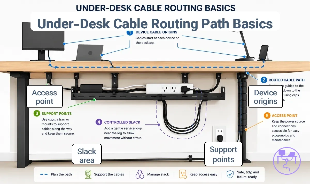
Under-desk cable routing works because each cable run is assigned a position, supported along its cable path, and given enough slack for movement or future adjustments. A cable tray and cable clips can help maintain cable support, but they do not replace the routing logic itself. When support and access are planned together, cables may be easier to reach and less likely to develop tangles or create avoidable safety concerns. Actual placement depends on device locations, desk underside space, and access requirements.
Under-desk cable routing is often confused with hiding visible cables, but the goals are different. Routing cables focuses on the cable path, support, access, and slack, while hiding visible wires focuses on appearance. Understanding this distinction prepares the next stage of route planning.
Plan the Cable Route Before Securing Cords
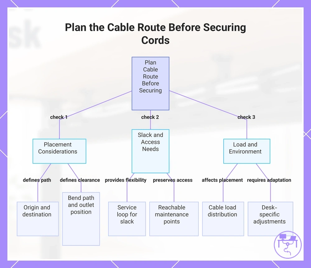
Cable route planning should happen before securing cords because route changes are easier to make before cables are tied, clipped, sleeved, or placed in a tray. A cable route should account for where cables begin, where they need to end, and how they will remain accessible afterward. The main decision frame is cable origin, destination, bend path, service loop, and access needs.
If device position, outlet location, or desk shape changes, the cable route may require a different route choice. A routing plan that suits one desk layout may not provide the same access or slack in another setup. Power-strip position and cable load can also influence placement along the underside space and affect reachable maintenance points. These conditions provide the basis for the checklist below.
Plan the Cable Route Before Securing Cords by verifying route conditions before any fastening action. The checklist separates placement-related criteria from conditions that influence slack and future access.
- Cable origin and destination determine the overall cable route and influence placement decisions.
- Bend path affects how the cable layout moves around desk structures, equipment, and obstacles.
- Outlet location and power-strip position influence route direction and cable grouping choices.
- Cable load can affect how cables are distributed across the route and maintenance areas.
- A service loop provides controlled slack that may help accommodate future equipment movement.
- Reachable maintenance points help preserve access without requiring major route changes.
For additional route-planning criteria, review how to plan cable routes before installation. Each verified condition supports a more informed routing decision before securing cords.
A fixed desk, a monitor arm, or a floor-to-desk route can change routing conditions because cable movement and slack requirements may differ. In these situations, route choice should account for changing cable positions and ongoing access needs. Apply the same planning checklist while adjusting for the specific desk condition.
This chart shows the key planning criteria to verify before securing cables, including placement, slack access, and load conditions.
Map Cable Paths From Devices to the Desk Underside
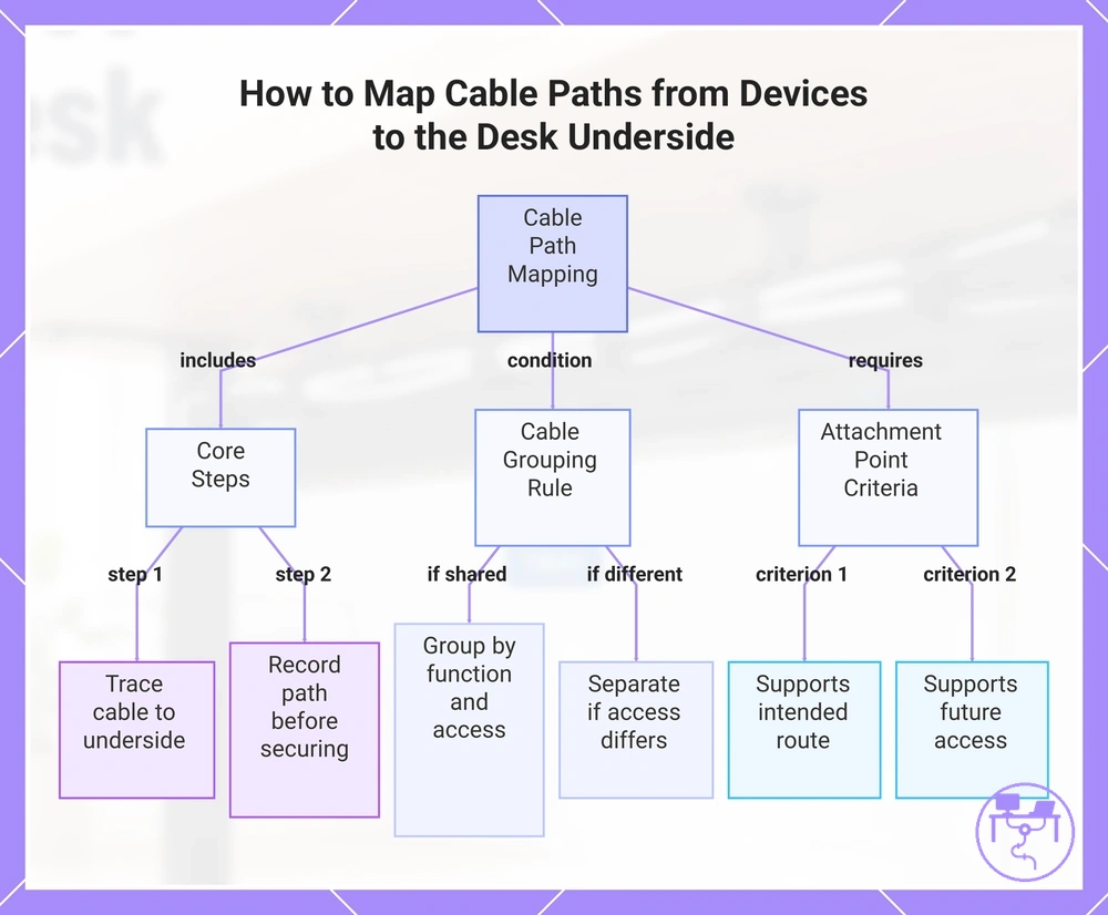
Map Cable Paths From Devices to the Desk Underside by tracing each device or peripheral from its cable source to the point where the cable joins the desk underside route. Record the cable path before choosing an attachment point or securing the cable. Trace each cable from source to underside point.
If multiple devices share a route, group cables by function and access need rather than tracing each cable individually. A monitor cable, power cable, and data cable may follow different underside paths when access requirements differ. Each cable group should connect to an attachment point that supports the intended underside route and future access need.
- Monitor cable source → underside path near the display area → attachment point near the display route → access need for display adjustment.
- Power cable source → underside path near the power route → attachment point near the power area → access need for power changes or maintenance.
- Data cable source → underside path along the data route → attachment point near the device path → access need for reconnection or upgrades.
- Shared cable group → combined cable path toward a desk underside support point → attachment point near the route transition → access need for future changes.
This chart shows the key steps, grouping rule, and attachment point criteria for mapping cable paths from devices to the desk underside.
Separate Power, Data, and Peripheral Cable Runs
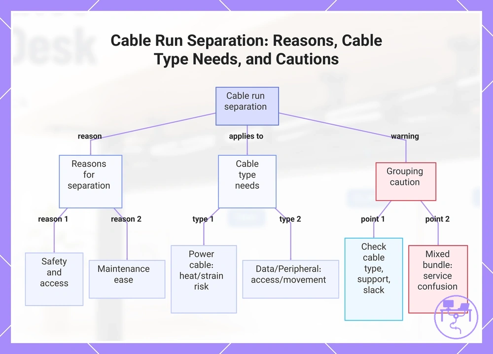
Separate Power, Data, and Peripheral Cable Runs when different cable types have different handling needs or access requirements. A shared cable run may be suitable in some setups, but separation can help when cable grouping contributes to heat, strain, or maintenance difficulties. The main reasons are safety, access, and maintenance.
Mixed cable bundles can become harder to manage when a power cable, data cable, and peripheral cable require different routing conditions. A power cable may follow a different cable run than a data cable when access needs or cable movement differ. Separation can also make individual cables easier to identify during maintenance and help preserve slack where needed. Use separation as a routing decision based on cable type and handling condition rather than as a universal rule.
Caution: Consider cable type, support, and slack before grouping multiple cable runs into a single bundle.
- Power cable → routed near an adapter or dense cable grouping → may benefit from separation when heat or strain becomes a concern.
- Data cable → requires regular access or reconnection → separation can simplify maintenance and cable tracing.
- Peripheral cable → subject to device changes or movement → separation may help preserve access and reduce cable strain.
- Mixed bundle → limited support or restricted slack → separation can help reduce service-related confusion during maintenance.
This chart explains the main reasons, cable type considerations, and grouping caution for separating power, data, and peripheral cable runs.
Choose Routing Hardware for the Main Cable Run
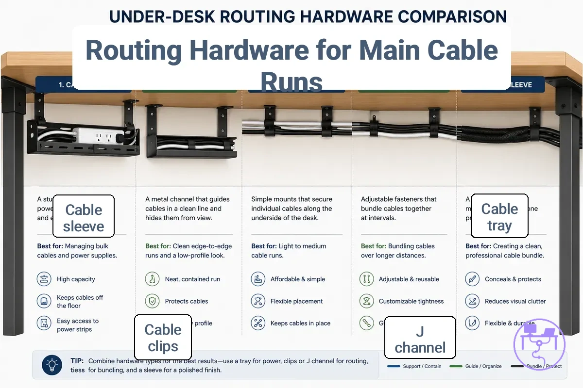
Routing hardware should match the function of the main cable run rather than serve as a general cable organizer. Different hardware types support different routing outcomes, access levels, and mounting conditions. Choose Routing Hardware for the Main Cable Run by matching the hardware to cable load, access level, and route direction.
Routing hardware includes categories such as a cable tray, J channel, clips, ties, and sleeve. A cable tray and J channel are commonly used to support a horizontal run along the desk underside, while clips and ties focus on cable positioning or grouping. A sleeve groups cables into a single bundle but may provide a different access level than open-support hardware. The comparison table below highlights how each category differs by routing job, access level, and cable load, and the image compares hardware by routing role and underside placement.
| Hardware type | Routing job | Access level | Best-fit condition | Watch-out |
|---|---|---|---|---|
| Cable tray | Support a main cable run | High | Moderate to higher cable load with frequent access | Requires suitable mounting space |
| J channel | Guide a horizontal run | Moderate | Structured underside routing with contained cables | Access may depend on channel design |
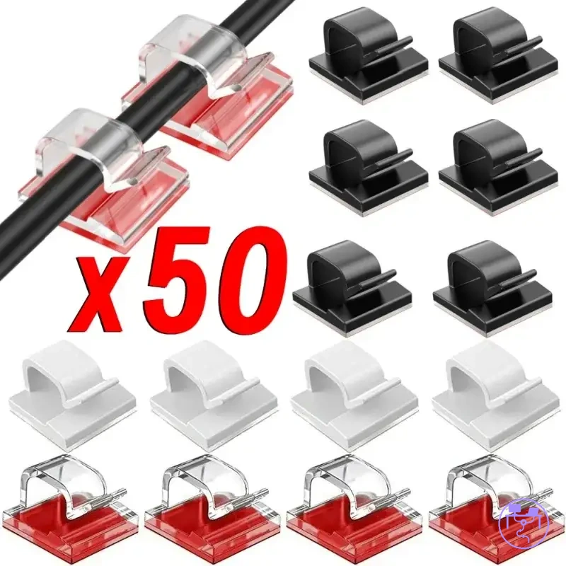
| Clips | Position individual cables | High | Light cable load and route control | Less suited to grouped cable runs |
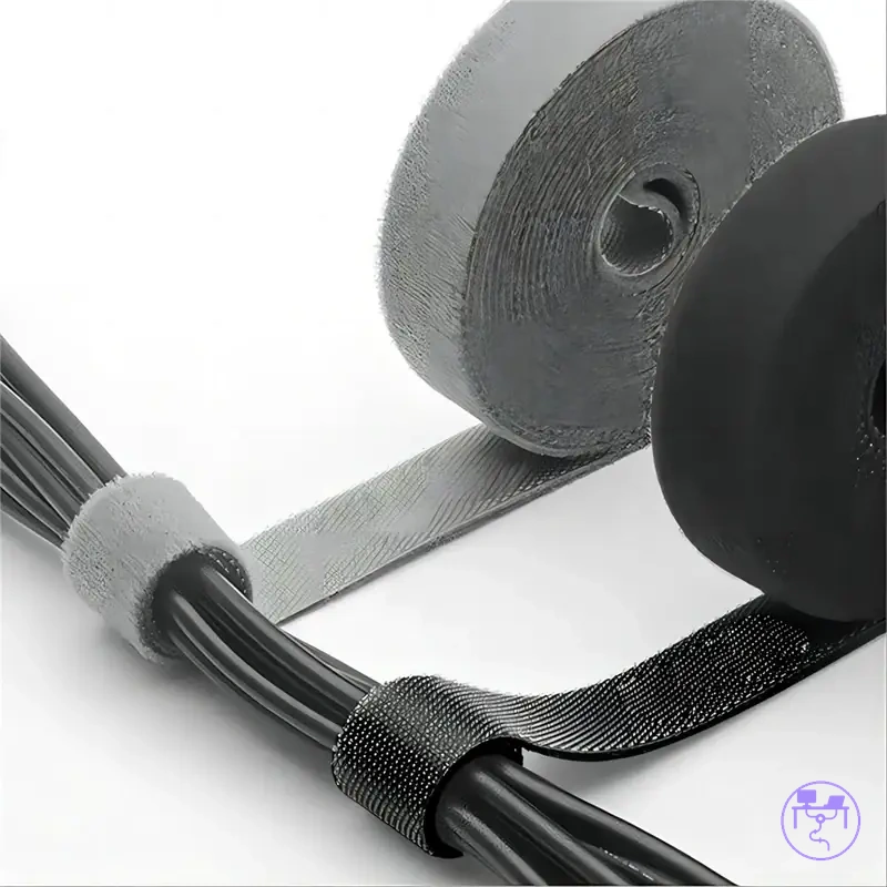
| Ties | Group cables together | Moderate | Cable grouping and route organization | May reduce removability if overused |
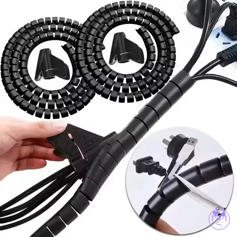
| Sleeve | Bundle multiple cables | Moderate | Grouped cables that follow the same route | Individual cable access may be reduced |
Table comparisons help identify which hardware attribute matches the routing objective without turning hardware selection into a product comparison exercise. For a broader comparison of hardware categories, see routing with trays raceways sleeves and clips.
Installation details belong after the hardware type has been selected because mounting methods vary by underside surface and hardware fit. This section focuses on selection attributes rather than installation procedures. For installation guidance, see install cable routing hardware.
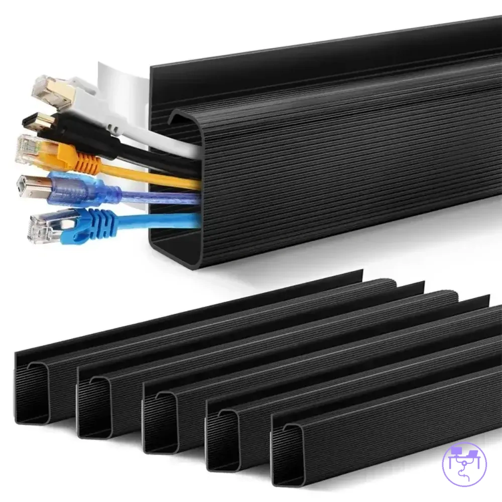
Trays and J Channels for Horizontal Routing
A tray or J channel can fit horizontal routing when cables need support along the back edge or underside of a desk. A tray may suit a larger cable bundle when capacity and open cable access are priorities, while a J channel may suit a contained horizontal run where cable visibility is a secondary concern. Both hold cable runs but differ in openness, capacity, and cable access for the horizontal routing use case.
Tray and J channel designs support the same routing direction but use different approaches to cable management. A tray typically offers greater openness and may simplify cable access when changes or maintenance are expected, while a J channel may create a more contained path along the mounting surface. The local tradeoff is that increased openness can improve access, while a more enclosed channel may reduce visibility but can increase service difficulty.
| Tray fit | J channel fit |
|---|---|
| Capacity: May suit a larger cable bundle when cable load increases. | Capacity: May suit a moderate horizontal run with a contained cable path. |
| Access: Open cable access can simplify cable changes and maintenance. | Access: Cable access may depend on channel shape and placement. |
| Mounting surface: Often spans a wider area of the desk underside. | Mounting surface: Often follows a defined section of the desk underside. |
| Cable visibility: Greater openness may leave cables more visible. | Cable visibility: A channel design may reduce cable visibility along the run. |
Clips, Ties, and Sleeves for Grouping Cables
Clips, ties, and sleeves support grouping cables after the main path has been chosen. These accessories help organize a cable group, manage strain relief, and influence cable access without changing the primary route. Their function is to support grouping and bundle control rather than provide main-route support.
Accessory choice depends on grip, removability, bundle size, and access requirements. Clips may suit cable groups that need frequent access, while ties may suit larger bundle sizes when controlled grouping is needed. Sleeves can help keep a cable group together for visual tidiness, while maintenance access may depend on how tightly cables are grouped. The practical tradeoff involves balancing grip, removability, and access.
- Clips: Can provide local grip along the underside while allowing relatively easy access and repositioning of individual cables.
- Ties: Can hold a larger bundle size together and support strain relief, but removability may decrease when ties are tightened more than necessary.
- Sleeves: Can group multiple cables into a single bundle for visual tidiness, though access to individual cables may require additional effort during maintenance.
- Straps or reusable ties: May suit cable groups that require repeated adjustments because removability is a higher priority.
Route Cables Along the Desk Underside
Route cables along the desk underside by following the planned cable path, grouping cables into a cable bundle, and supporting the route with clips or a tray where needed. The goal is to keep the cable path organized while preserving slack allowance, bend radius, and future access. The action sequence is anchor point selection, cable routing, support placement, slack management, and access verification.
If the planned route already aligns with the selected hardware, the cable bundle can move from a planned path to a supported underside route without changing the layout. A tray route may suit a larger cable bundle, while a clip-supported route may suit cables that require more direct access. The steps below demonstrate how to move from a planned route to a secured cable run.
Route Cables Along the Desk Underside using the visual below to identify the anchor point, cable bundle path, support locations, slack allowance, and final access check.
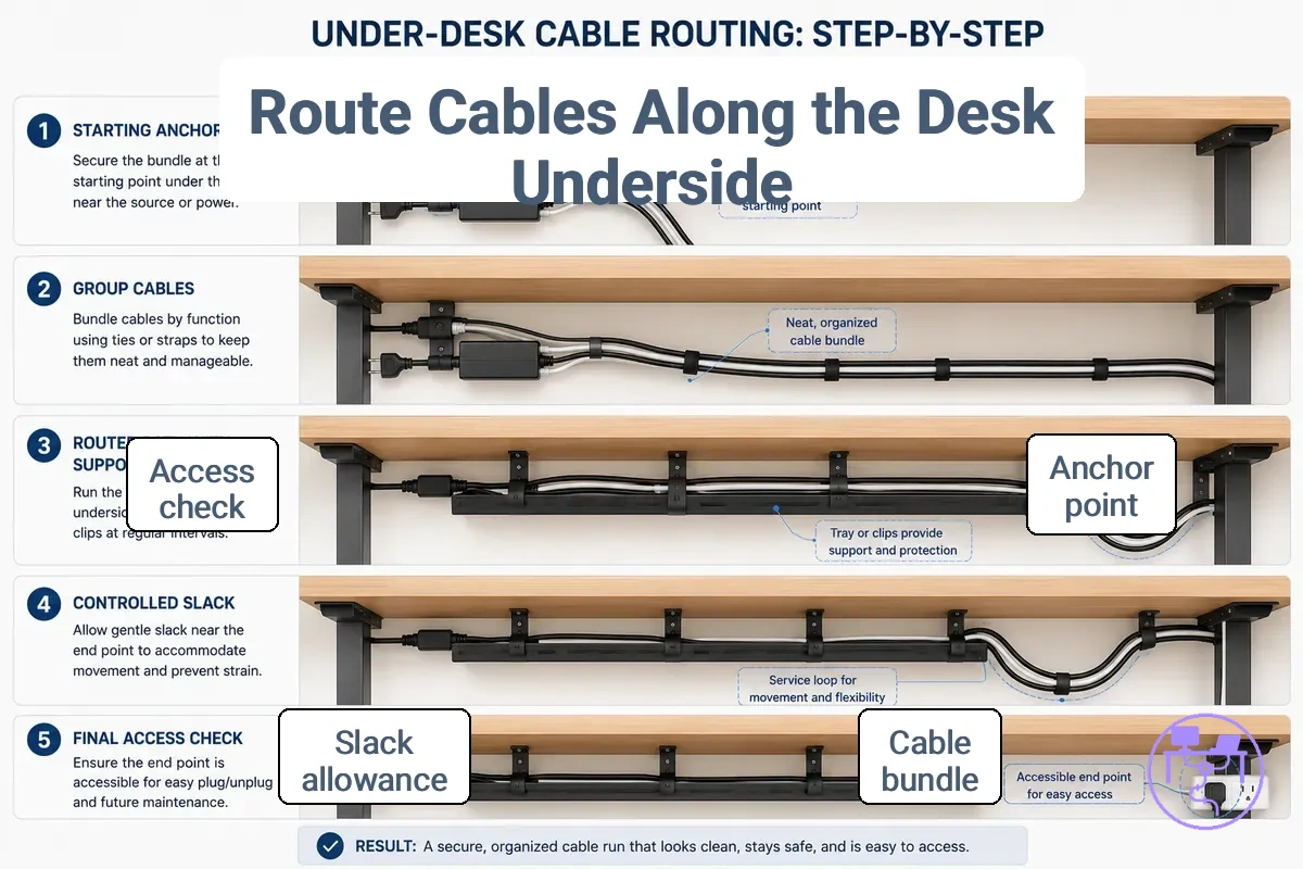
- Select the first anchor point along the desk underside; if the cable path begins near a device cluster, use that location as the starting reference so the cable bundle follows a defined route.
- Guide the cable bundle along the planned cable path; when clips or a tray align with the route, the cable run can remain supported and easier to organize.
- Maintain attachment spacing that matches the cable load and route shape; when support points are distributed appropriately, the cable bundle may remain more stable along the underside.
- Leave a slack allowance near devices or movement points; when equipment position changes, the cable path may adapt with less strain.
- Check the bend radius at turns and transitions; when bends remain gradual, cables may be easier to manage and access later.
- Perform an access check along the entire route; when connectors, adjustments, and maintenance points remain reachable, the cable run may be easier to modify without rerouting major sections.
Routing focuses on the cable path and support sequence rather than hardware installation details. Complete a final check by confirming that the cable bundle still has suitable access, slack allowance, and bend flexibility after routing. Finish with access, slack, and strain verification.
Secure Cables Without Blocking Access
Secure cables by supporting them at each attachment point while keeping access to ports, plugs, and adapters available for future changes or maintenance. The amount of pressure at an attachment point and the spacing between support points may vary based on cable thickness, cable type, and access needs. Cable support can reduce sagging, but support must not block access.
Attachment point decisions depend on pressure, spacing, and release access requirements. If clips or ties apply more pressure than needed, ports, plugs, or adapters may become harder to reach when equipment changes occur. Before tightening a support point, verify that release access remains available and complete the release-access check.
- Confirm that ports remain reachable without removing multiple support points.
- Check that plugs can disconnect when needed without excessive pressure on the cable.
- Verify that adapters remain accessible after cables are secured.
- Ensure that clips or ties still allow release access for future maintenance.
Route Cables From Floor to Desk
A floor-to-desk cable run should move from the outlet position or floor cable path to the desk underside with support before it reaches the entry point. The route should avoid loose cable across walking areas and should not pull tightly against plugs or adapters. The local risks are trip hazard, tension, and missing slack.
If the outlet position is on the floor or wall below the desk, vertical support should guide the cable upward before the cable reaches the desk entry point. A fixed desk may need only a stable vertical cable run, while a height-adjustable desk may need more movement range before the cable reaches the underside. The entry point should be placed where the cable can turn toward the underside route without creating strain.
- Identify the outlet position; if the cable starts near a walking path, route the floor-to-desk cable run away from foot traffic to reduce trip hazard risk.
- Add vertical support where the cable rises; when the cable is supported upward, the visible tangle near the floor may be reduced.
- Leave a slack loop near the transition point; when the desk or device moves, the cable can move with less strain.
- Choose the entry point under the desk; if the cable enters near the main underside route, the cable can join the path with fewer unsupported bends.
- Check movement range before final positioning; if the desk height or device position changes, the slack loop should allow movement without pulling tight.
Control Cable Length, Slack, and Labels
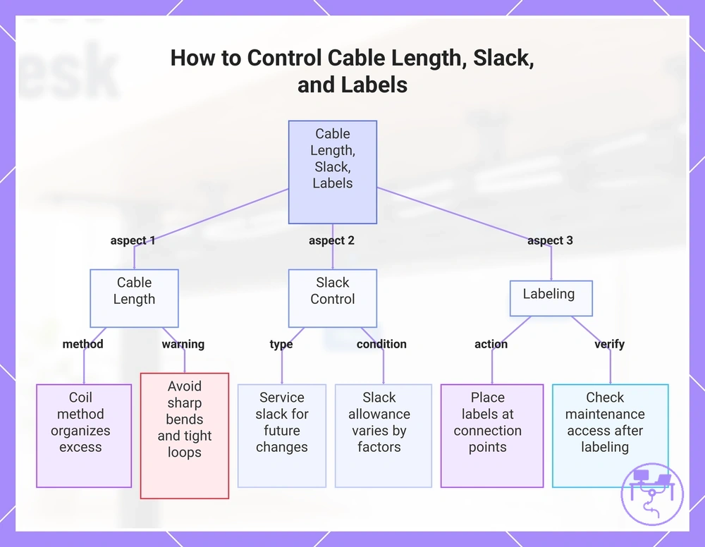
Control cable length, slack, and labels after the main route is secured so cables remain organized without reducing maintenance access. Excess cable, service slack, and cable labels should be adjusted based on how often equipment may change or move. Effective slack control depends on access needs and future changes.
Cable length depends on the route distance, device position, and maintenance requirements. When excess cable remains after routing, a coil method can help keep cord length organized near a monitor, power strip, or docking area. The coil method should avoid sharp bends or overly tight loops because tight coils may limit cable flexibility.
Tie pressure should hold cables together without compressing them more than necessary. Slack allowance may vary by device movement, cable type, and maintenance frequency. Service slack supports future adjustments and connects cable slack to movement and maintenance needs.
Label position should stay visible where cables connect, separate, or enter a grouped route. Labels can help identify cable purpose during future changes, while maintenance access still depends on reachable connectors and service points. Control Cable Length, Slack, and Labels using the checklist below to verify slack, labels, and future maintenance access.
- Coil excess cable using a coil method that keeps cable length organized and accessible for future changes.
- Apply tie pressure that supports cable organization while allowing cable movement when maintenance is needed.
- Leave service slack where monitors, docking areas, or connected devices may change position.
- Place labels near connection points so cable identification remains easier during maintenance.
- Check maintenance access after labeling and grouping to confirm connectors remain reachable.
Cable length, slack allowance, and label position are most useful when they support future changes rather than visual neatness alone. Prioritize maintenance access, service slack, and clear identification before making further adjustments.
The products below are useful examples for comparing available options. Before buying, check that the compatibility criteria, key features, and product details match your needs.
This chart shows how to manage cable length, slack, and labels to maintain organization and future maintenance access.
Safe Routing Around Power Strips and Adapters
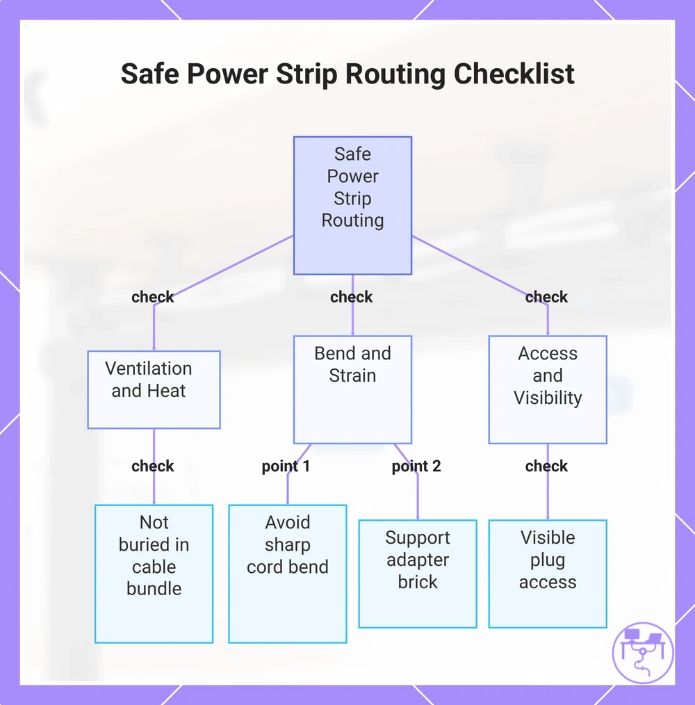
Safe Routing Around Power Strips and Adapters depends on keeping the power strip, adapter, and power cord reachable while avoiding unnecessary pressure or blocked airflow. A cable path near power components should allow access to plugs and should not force a tight cord bend. Heat, strain, access, and path are the main safety variables.
Adapter bricks and power strips can create routing problems when the cable path traps heat, pulls the power cord, or blocks plug access. Place the adapter and power strip where plug direction and load access remain visible enough for checks or changes. Keep ventilation available and avoid sharp cord bend conditions that may add strain.
Safe Routing Around Power Strips and Adapters should be checked before the power cable is bundled with the rest of the route. Use the caution checklist below to verify ventilation, bend, access, strain, and load visibility before moving into deeper safety guidance.
- Check that the power strip and adapter have ventilation rather than being buried inside a tight cable bundle.
- Confirm that plug direction does not force the power cord into a sharp bend.
- Keep load access visible enough to inspect or disconnect plugs when needed.
- Route the cable path so the adapter brick is supported without hanging strain on the cord.
- Keep power-routing decisions consistent with manufacturer instructions and local safety requirements.
This section covers routing-level safety only, not electrical code advice, overload guidance, or guarantees that a setup is safe. For deeper power-cord guidance, see how to route power cables safely.
This chart shows the main safety variables and verification checks for routing cables around power strips and adapters.
Fix Loose, Dangling, or Tangled Cable Runs
When loose cables, dangling cables, tangled cables, or strained cables appear after routing, the likely cause is often related to route placement, cable support, slack control, or cable grouping. A visible symptom does not point to a single cause, so diagnosis should happen before any correction is made. Most cable-routing issues connect back to route, support, slack, or grouping conditions.
Loose cables may result from an unsupported section of the route, while tangled cables may indicate that cable grouping no longer matches current use. A safe correction depends on checking the symptom first and then matching the correction to the likely cause. The diagnostic table below helps identify common symptoms and possible correction paths.
Fix Loose, Dangling, or Tangled Cable Runs by comparing each symptom with its likely cause and selecting a safe correction before making route changes. For broader troubleshooting patterns, see how to fix bad cable routing.
| Symptom | Likely cause | Safe correction | When to re-plan |
|---|---|---|---|
| Sagging cable run | Cable support may be too widely spaced or missing. | Add or adjust a support point along the cable bundle. | Re-plan the route if sagging continues after support is corrected. |
| Loose clip paths | The clip path may no longer match the cable route. | Reposition the cable support to follow the current route. | Re-plan the route if cable movement repeatedly pulls away from support points. |
| Tangled bundles | Grouping with sleeves or ties may no longer match current cable connections. | Separate and regroup cables using a more suitable bundle structure. | Re-plan the route if cable clutter returns after regrouping. |
| Over-tightened cords | Strained cables may result from excess tension or a restricted bend. | Reduce tension and restore access around the affected section. | Re-plan the route if the cable path cannot support movement without strain. |
Safe correction depends on matching the symptom to a likely cause rather than applying the same fix everywhere. Use cable support, grouping, tension, and access checks as correction criteria before deciding to re-plan the route. Re-plan the route when a local correction cannot resolve the underlying cable-routing issue.
The products below are useful examples for comparing available options. Before buying, check that the compatibility criteria, key features, and product details match your needs.