Desk Cable Management System Planning Checklist Before Installation
A desk cable management system planning checklist helps prevent poor fit, strained cable paths, and unsafe routing before installation. It checks whether the desk setup, cable load, power access, and under-desk space are ready for installation readiness.
A desk cable management planning checklist is a pre-installation review of the system, desk, cables, power strip, mounting method, and service access. It helps confirm where parts may fit, where cables can travel, and which areas need to stay reachable. This is planning, not the later installation process.
A light laptop desk may need a simple cable organizer setup, while a heavier workstation may need more careful routing, power strip placement, and mounting readiness. Desk shape, cable load, and power access can change the under-desk cable plan. Start by checking the existing desk setup as the first planning input.
The desk cable management system planning checklist organizes installation readiness by desk, cable, power, and mounting conditions.
- Check the desk condition, under-desk space, and clearance before choosing where hardware may sit.
- Map cable paths from devices to power access, connection points, and exit areas.
- Place the power strip where switch access, plug direction, ventilation, and cable strain can be managed for the specific layout.
- Match the mounting method to desk material, edge space, surface condition, and removability needs.
- Keep service access open for cables, adapters, clips, trays, or ties that may need adjustment later.
Desk Setup Inventory Before Cable Management Installation
A desk setup inventory identifies every cable source, cable destination, and access need before cable paths or mounting positions are chosen. Count the devices, cables, adapters, outlets, connection locations, desk openings, and access zones that the desk cable management system must work around.
A light laptop setup may only need a small cable count and a few fixed connection points, while a heavier workstation setup may need deeper planning because more devices, adapters, and outlets can change routing and access needs. Use the desk cable management system hub as the parent context for the full setup, then use this inventory to organize what is fixed, what moves, and what needs access.
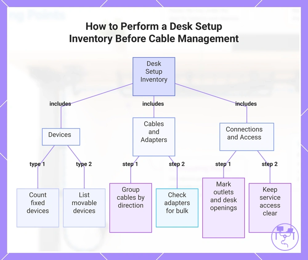
The desk setup inventory organizes devices, cables, adapters, outlets, and connection locations before the cable management layout is planned.
- Count fixed devices that stay on the desk because each device creates a cable source or destination.
- List movable devices that may need extra reach, removable access, or a less restricted cable path.
- Group cables by direction so the planned route follows connection locations instead of crossing the desk underside randomly.
- Check adapters for bulk because large adapters may affect outlet reach, power strip position, and access zones.
- Mark outlets and desk openings so cable paths can connect power access with entry and exit points.
- Keep service access clear for plugs, chargers, and cables that may need adjustment after installation.
This chart shows the key categories and actions in a desk setup inventory, helping identify devices, cables, connections, and access needs before planning cable paths.
Devices, Cables, Adapters, and Connection Points
Every device and adapter creates a cable source, cable destination, or access need that affects routing decisions. Count connection points before planning cable direction, then use the checks below to map sources, destinations, reach, and access requirements.
- Device → fixed desk position → creates a stable cable source and cable destination that guides routing.
- Peripheral → may move during use → can require additional reach and easier access along the cable path.
- Adapter or power brick → increased bulk → may affect outlet space and future access needs.
- Display cable → connection point between screen and device → influences cable direction and routing path.
- Connection point → located above or below the work surface → affects cable destination planning and route length.
- Charger cable → for example, from a laptop to a nearby outlet → helps identify required reach while preserving access.
Desk Underside Measurements and Clearance Checks
Desk underside measurements confirm whether the desk can hold planned cable management parts before installation. Check width, depth, desk thickness, and available under-desk space before selecting placement areas. These measurements establish the mounting area, edge clearance, and usable clearance to review.
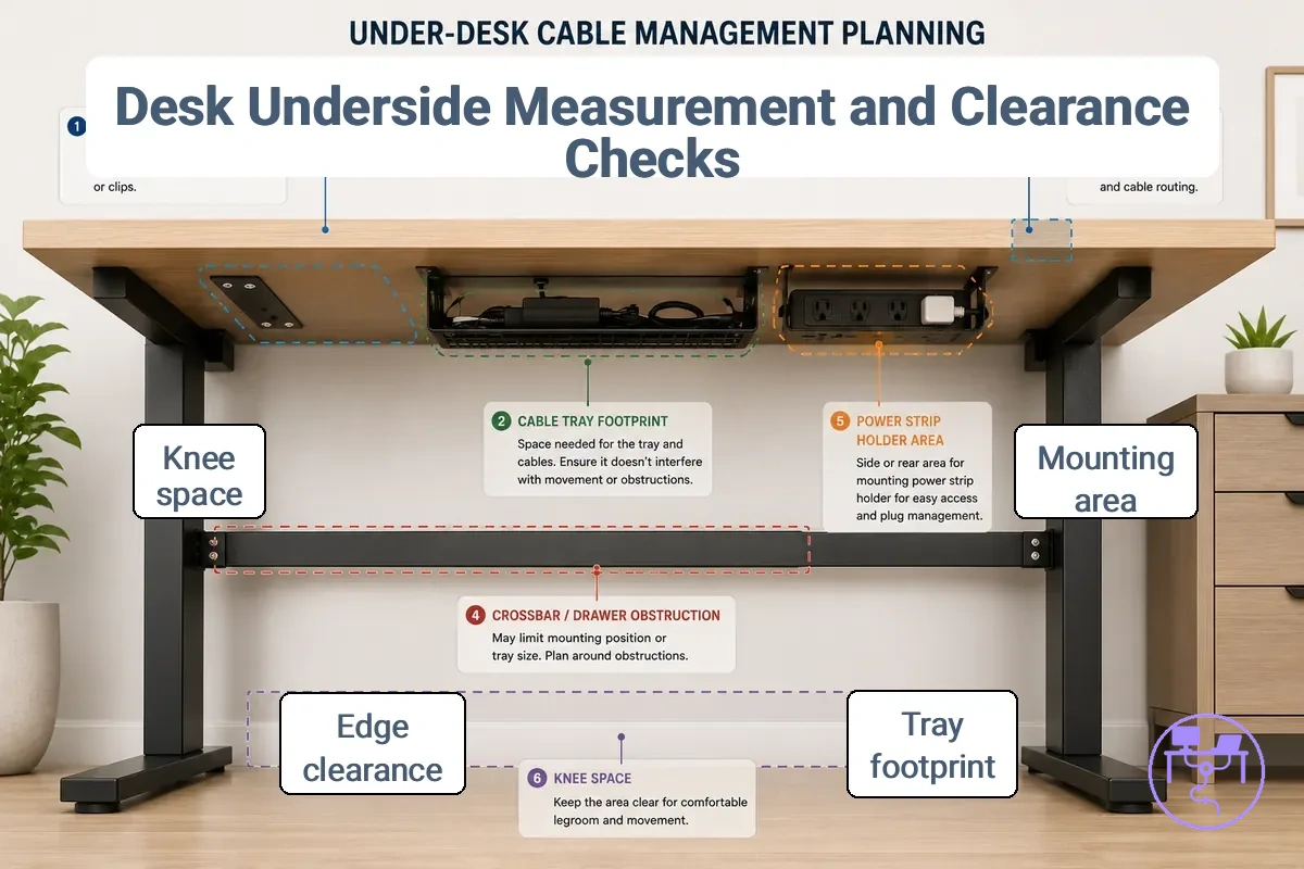
Obstructions can reduce the amount of mounting space available under a desk. Crossbars, drawers, monitor arms, and structural supports may limit where a cable tray, clips, sleeves, grommets, or a power strip holder can be positioned. When usable clearance is reduced, placement options may depend on the desk construction and the hardware being considered.
Desk underside measurements and clearance checks prepare the information needed for installation planning, but they do not replace a full desk fit evaluation. For a deeper fit assessment, check desk compatibility.
Desk underside measurements and clearance checks determine safe placement and usable clearance before mounting decisions are made. Use the checklist below to review clear space, blocked space, and access conditions.
- Width: Available mounting area width affects where a cable tray or power strip holder may be positioned.
- Depth: Usable depth influences placement options while keeping components reachable.
- Desk thickness: Thickness can affect clamp clearance, screw depth, and mounting method options.
- Edge clearance: Limited edge clearance may reduce available attachment locations.
- Crossbars: Crossbars can block part of the mounting area and reduce usable clearance.
- Drawers or monitor arms: Existing hardware may occupy space needed for routing or attachment.
- Knee space: Clearance below the desk should remain usable after hardware placement.
- Service access: Reachable access space can help when cables or components need adjustment later.
Cable Tray Length, Depth, and Load Space
Cable tray length and tray depth should match cable volume, cable bundle size, adapter bulk, and access clearance needs. Tray size depends on the space required for cables, power strip placement, and future service access, while available load space may vary by cable capacity and hardware dimensions. The table below organizes the main tray sizing variables.
| Entity/part | Attribute/criterion | Value/condition | Effect/risk/decision |
|---|---|---|---|
| Cable tray length | Cable volume | Higher or lower cable count | Tray length should match the cable bundle and planned access needs |
| Tray depth | Load space | Power strip or larger components present | Additional depth may improve clearance and cable organization |
| Cable bundle | Bundle thickness | Thicker grouped cables | More cable capacity may be needed to maintain service access |
| Adapter bulk | Physical size | Larger adapters or power bricks | Bulk may reduce clearance and affect accessible service space |
| Access clearance | Service access | Frequent cable adjustments expected | Leave reachable space for future cable access and maintenance |
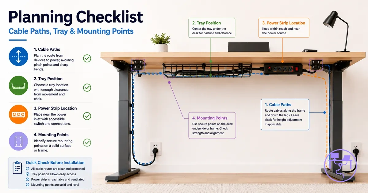
Cable Route Planning Under the Desk
Cable route planning under the desk prevents cable tension, crossing paths, and blocked access before clips, trays, sleeves, or holders are mounted. A routing plan connects cable origin points to destinations while accounting for entry points, exit points, route direction, and slack. Planning the route first establishes the main path variables before hardware placement.
Cable route planning under the desk and the image below demonstrate route direction, entry points, exit points, and slack zones before hardware placement. The example highlights the areas to inspect while defining a cable path.
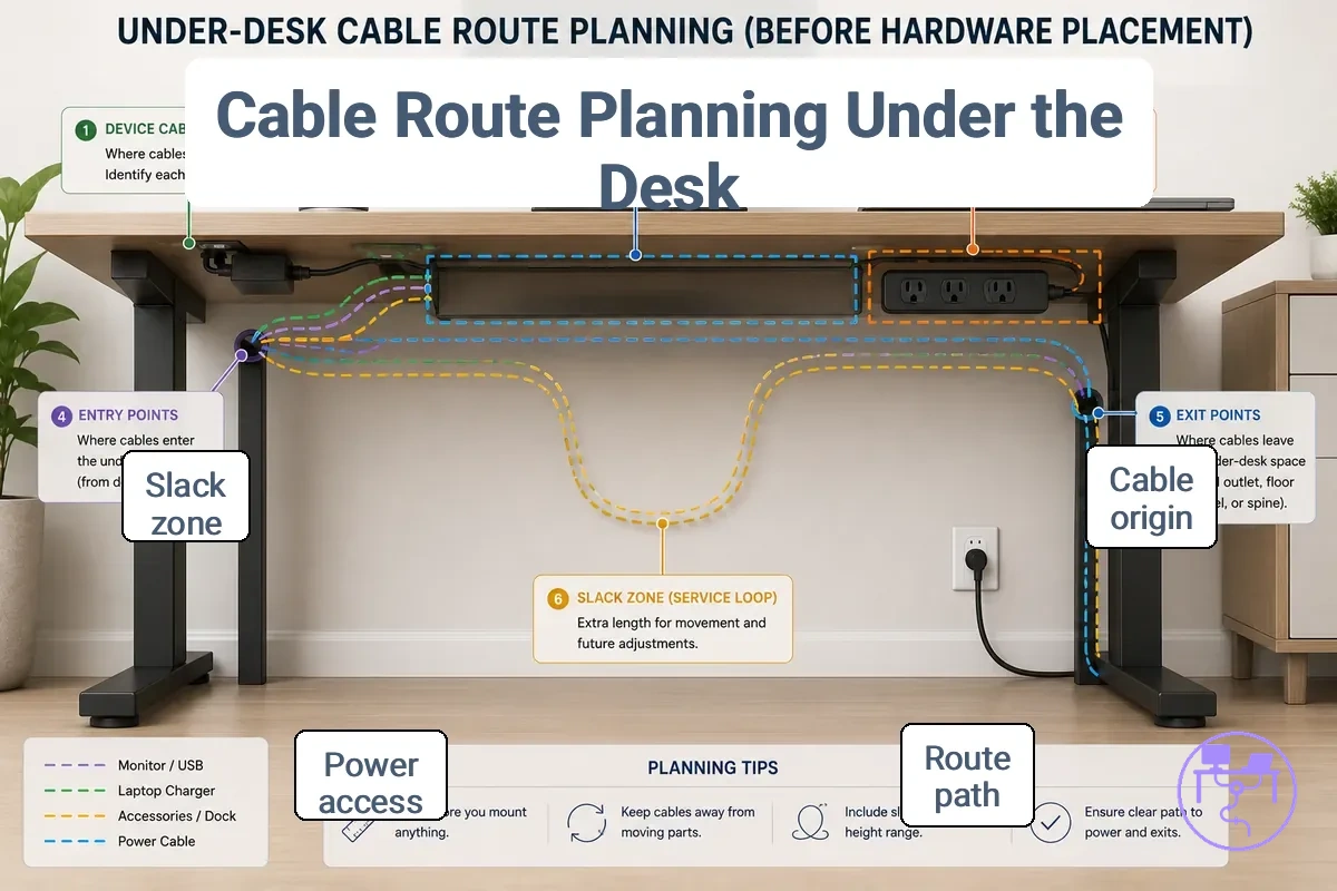
Cable route planning under the desk helps identify how cables should travel between a cable origin and a cable destination. Route direction affects where cables enter and leave the under-desk path, while slack may be needed when devices move or require repositioning. Cable separation can help organize power cables and signal cables when different paths improve access. Future access should remain part of the routing plan so cables can be reached if rerouting becomes necessary.
Cable route planning under the desk connects devices, desk entry points, power access, and future service needs. Detailed cable placement belongs to the next stage after the route plan is established. For execution-focused guidance, route cables after planning.
- Cable origin: Identify where each cable starts because origin points influence route direction.
- Entry points and exit points: Check where cables enter and leave the planned path because these locations affect route continuity.
- Route direction: Choose a path that reduces unnecessary crossing and supports cable separation.
- Slack: Leave enough slack when device movement or repositioning may change cable reach requirements.
- Cable separation: Separate cable groups when different paths may improve access or organization.
- Bend tolerance: Plan route changes carefully because tighter bends may affect path flexibility.
- Future access: Keep important sections of the routing plan reachable when adjustments or rerouting may be needed later.
Route Length, Slack, and Cable Exit Points
Route length and slack must prevent tension while preserving service access from the cable origin to the destination. Cable exit points should support cable reach without creating sharp bends or unnecessary visible clutter. Use the checks below to verify local route conditions before routing decisions are finalized.
- Route length: Confirm that cable path length allows the cable to reach its destination without tension.
- Slack: Leave a slack reserve when desk movement or repositioning may change cable reach requirements; a moving desk may need more allowance than a fixed desk.
- Sharp bends: Check route changes carefully because tighter bends may increase strain along the cable path.
- Entry point: Verify that the entry point supports a smooth path without forcing abrupt direction changes.
- Cable exit points: Review each exit location because a poorly placed exit point may create visible cable sections or restricted reach.
- Service access: Keep important cable sections reachable when future access or rerouting may be required.
Cable Grouping, Bundling, and Access Needs
Cable grouping should follow access needs rather than appearance alone. Bundling fixed cables can reduce loose runs, but removable chargers and frequently moved cables may need separate access for reach, rerouting, and maintenance. Use the mini-checklist below to decide which cable group should be bundled or kept separate.
- Power cords: Group fixed power cords when they share a stable route and do not need frequent removal.
- Display cables: Bundle display cables with fixed monitor and power cables when the screen position is unlikely to change.
- Peripheral cables: Keep peripheral cables easier to access when the device may move or be disconnected.
- Removable chargers: Keep a laptop charger separate from fixed monitor and power cables when reuse or reach changes often.
- Frequently moved cables: Separate cables that need regular adjustment so the fastening choice does not make rerouting difficult.
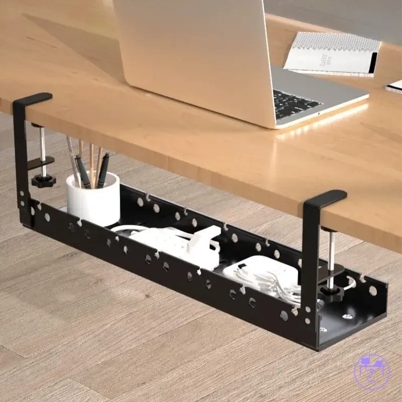
Power Strip Placement Before Mounting
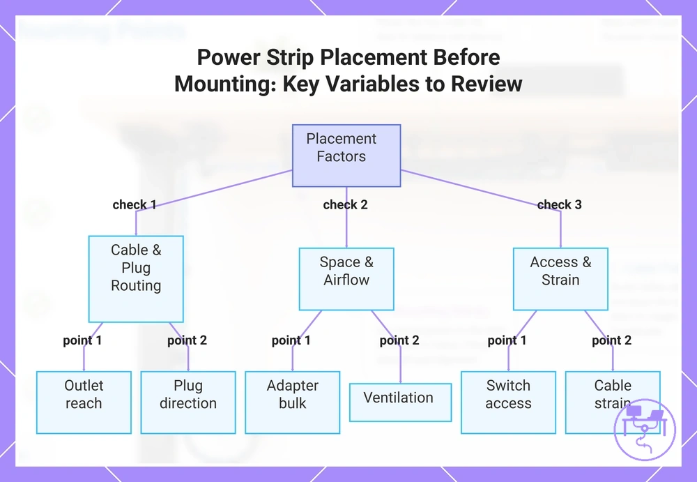
Power strip placement before mounting should remain reachable, ventilated, and aware of cable strain. The power strip position should support outlet reach without forcing cables into unnecessary tension or awkward routing. Outlet reach, plug direction, adapter bulk, ventilation, switch access, and cable strain are the main placement variables to review.
Adapter bulk can reduce usable space around outlets and may affect how plugs fit within the planned layout. Plug direction can influence cable clearance when cords leave the power strip and enter the cable path. Switch access should remain practical after the tray or holder is installed, and floor clearance may help keep the power strip easier to reach. These placement choices support practical safety awareness when access and ventilation remain available.
Power strip placement before mounting affects reach, ventilation, cable strain, switch access, and cable clearance. Use the checklist below to review placement conditions before selecting a mounting location.
- Outlet reach: Keep the power strip close enough to the outlet so cable routing does not create unnecessary strain.
- Plug direction: Check how plugs leave the power strip because cable direction may affect clearance and access.
- Adapter bulk: Leave enough surrounding space when larger adapters may occupy nearby outlet positions.
- Ventilation: Choose a position where airflow is less likely to be restricted by nearby objects or enclosed spaces.
- Switch access: Keep switches reachable after mounting so routine access does not require removing hardware.
- Cable strain: Avoid placement that may pull, stretch, or sharply redirect connected cables.
- Floor clearance: Maintain reasonable clearance from the floor when the layout may expose the power strip to contact or obstruction.
Detailed power-cord safety considerations belong in the dedicated safety context. See power cord safety checks.
This chart shows the main placement variables to review before mounting a power strip, including cable routing, space, airflow, access, and cable strain.
Outlet Direction, Ventilation, and Reach
Outlet direction, ventilation, and reach determine whether the selected power strip position remains usable after mounting. Check plug clearance, airflow, switch visibility, adapter spacing, and cable reach before finalizing the location, then use the checks below to confirm local placement conditions.
- Outlet direction: Verify that outlet orientation supports a clear cable path and practical power access.
- Plug clearance: Confirm that connected plugs have enough space so nearby cables or hardware do not restrict access.
- Airflow: Check that surrounding objects are less likely to block airflow because reduced ventilation may limit usable placement options.
- Switch visibility: Keep switches visible and reachable so routine access remains practical after installation.
- Adapter spacing: A bulky adapter may block a nearby outlet or reduce available clearance, so check spacing before mounting.
- Reach: Confirm that cable reach supports the planned position without creating unnecessary cable strain.
Tray, Clip, Sleeve, and Grommet Placement Checks
Tray, clip, sleeve, and grommet placement checks help match each cable management part to a specific planning role before installation. Each cable management part supports a different placement need based on cable routing, access, cable grouping, or desk entry points. The main parts to review are the tray, clip, sleeve, grommet, and holder.
Tray, clip, sleeve, and grommet placement checks are easier to review when the image labels where each part fits in the planned layout.
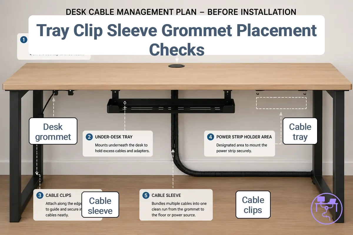
Placement depends on cable type, access requirements, cable grouping, and the available mounting surface. A tray may suit a cable bundle when underside placement is available, while a clip may help guide a single cable path. A sleeve may organize a visible cable group, and a grommet may support cable entry through a desk opening. The table below compares the main placement roles.
| Part | Best placement role | Condition to check | Planning outcome |
|---|---|---|---|
| Tray | Support a cable bundle | Available underside placement and cable load | Organized cable routing area |
| Clip | Guide a single cable run | Mounting surface and access needs | Improved route control |
| Sleeve | Group visible cables | Cable group size and flexibility needs | More organized visible run |
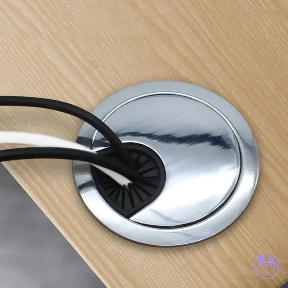
| Grommet | Manage a desk entry point | Desk opening and cable path location | Cleaner cable transition |
| Holder | Support accessory positioning | Access requirements and mounting surface | More stable component placement |
For a deeper explanation of individual cable management components, see parts to plan around.
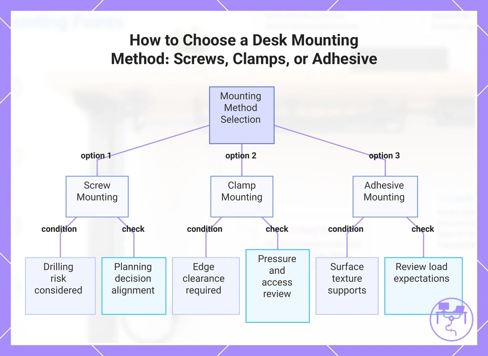
Mounting Method Checks for Screws, Clamps, and Adhesive Parts
Mounting method suitability depends on desk condition, desk material, desk thickness, load, and removability requirements. A mounting method that suits one desk setup may be less suitable for another when holding limits or surface conditions differ. The main options to compare are screws, clamps, and adhesive parts.
Desk material, desk thickness, load, and removability should be reviewed before choosing a mounting method. Screw mounting may depend on whether the desk can accommodate drilling, while clamp mounting depends on edge clearance and contact pressure. Adhesive mounting may depend on surface texture and expected load. Mounting method checks for screws, clamps, and adhesive parts become clearer when each option is compared against desk condition and planning outcome. Use the compatibility checklist below to review the main decision signals.
Surface condition and removability can influence mounting outcomes. Adhesive parts may create residue risk when removal is required, while clamp mounting may create pressure-related concerns when edge conditions are limited. Screw mounting may introduce drilling risk when future setup changes make removability important.
- Screws: Desk material and desk thickness support drilling → drilling risk should be considered → review whether the attachment approach aligns with the planning decision.
- Clamps: Adequate edge clearance is available → pressure may affect certain desk conditions → review removability and access requirements.
- Adhesive parts: Surface texture supports attachment → holding limit may vary with load and surface condition → review load expectations before installation.
- No-drill mounting: Removability is a priority → attachment suitability may depend on surface and edge conditions → review whether the setup supports future changes.
The planning decision should compare desk condition, load, holding limit, and removability rather than relying on a single mounting method preference. When more than one option appears suitable, the choice may depend on future access needs and installation constraints. Use this comparison to select the right setup before choosing installation hardware.
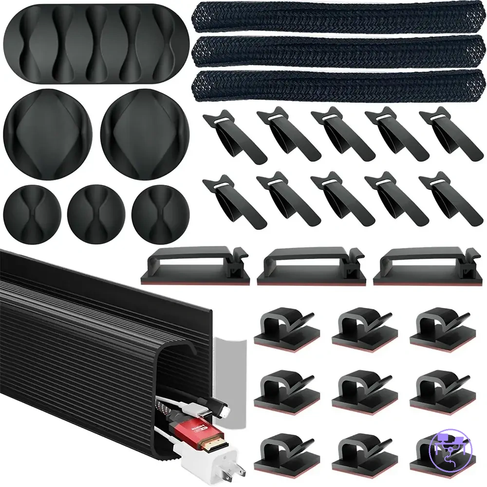
The products below are useful examples for comparing available options. Before buying, check that the compatibility criteria, key features, and product details match your needs.

This chart compares the three main mounting methods against key conditions and checks to help you select the right setup based on desk condition, load, and removability.
No-Drill Mounting Limits and Surface Risks
No-drill mounting may work only when the surface texture, cable weight, heat exposure, and removal needs support the attachment method. Adhesive pads, clamps, smooth surfaces, textured surfaces, and residue risk should be checked before relying on removable mounting. No-drill mounting limits and surface risks are easier to compare through the contrast below.
| Suitable conditions | Risk conditions |
|---|---|
|
|
Pre-installation Safety and Access Checks
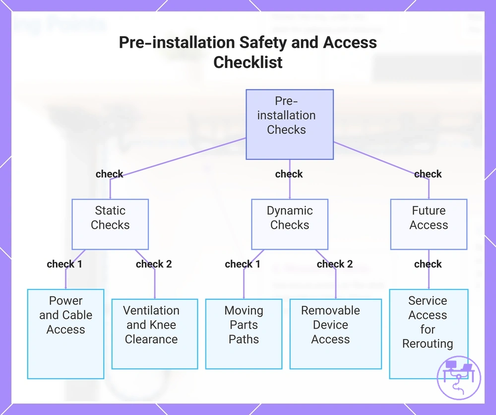
Pre-installation safety and access checks verify whether the planned layout remains usable before any part is fixed in place. Safety checks and access checks should confirm that power access, cable strain, ventilation, knee clearance, and service access remain practical after installation. Use the final safety checklist below to review the planned layout before fixing any components.
For desks that move, fold, or include drawers and crossbars, access checks should account for changing clearances and movement paths. Moving parts may alter cable routing, while removable devices may require adjustment access for future changes or rerouting. If movement or obstructions could restrict access or increase cable strain, the layout may need adjustment before installation.
- Power access: Verify that outlets and controls remain reachable to help prevent blocked access after installation.
- Cable strain: Check that cable paths allow adequate reach to help prevent tension and difficult servicing.
- Ventilation: Confirm that airflow remains available where enclosed areas could restrict heat dissipation.
- Knee clearance: Verify that installed parts and cable routes do not reduce comfortable leg space.
- Moving parts: Check drawers, folding sections, and desk movement paths to help prevent pinched or obstructed cables.
- Removable devices: Confirm that chargers, peripherals, and detachable components remain accessible for removal or reconnection.
- Future adjustment: Leave service access for rerouting, cable changes, or layout modifications when setup requirements change.
This chart organizes the essential pre-installation checks into static layout, dynamic movement, and future access categories to verify usability before fixing components.
Installation-ready Desk Cable Management Checklist
An installation-ready checklist confirms whether desk cable management planning is complete before installation begins. Readiness depends on verified measurements, route choices, power placement, mounting method decisions, safety checks, and future access conditions.
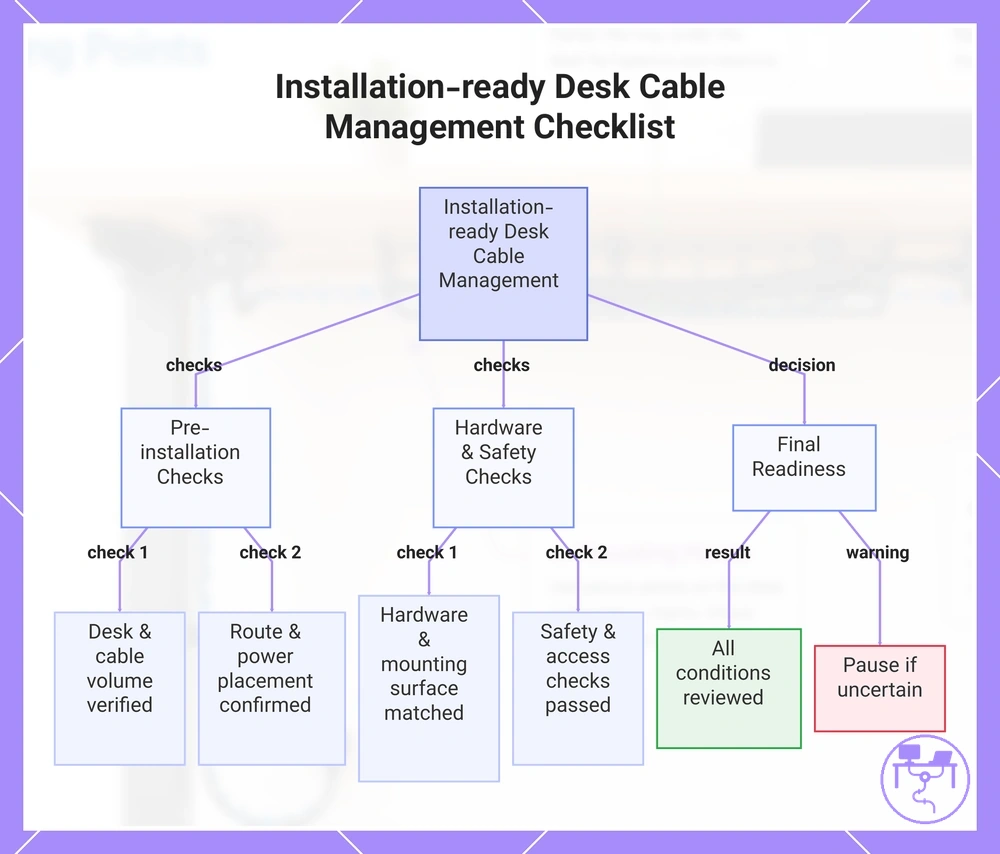
The installation-ready desk cable management checklist turns planning decisions into simple verification items. Each verification item should confirm that a condition has already been reviewed rather than introduce a new decision. Use the checklist below for the final readiness check.
- Desk: Desk dimensions, clearance areas, and obstructions have been verified.
- Cable load: Planned cable volume matches the intended cable management capacity.
- Route choices: Cable paths, entry points, exit points, and slack requirements have been reviewed.
- Power placement: Power strip position remains reachable and supports the planned layout.
- Hardware placement: Tray, clip, sleeve, grommet, or holder locations have been confirmed.
- Mounting surface: Surface conditions match the selected mounting method when installation proceeds.
- Safety: Cable strain, ventilation, movement clearance, and knee clearance have been checked.
- Future access: Service access and future adjustment needs remain available.
- Readiness decision: No unresolved planning condition remains that could affect installation.
If any measurement, route choice, power placement, or mounting condition remains uncertain, pause installation and recheck the plan before fixing components in place. Uncertain conditions may require adjustment before readiness can be confirmed.
Proceed only when the installation-ready checklist supports the planned layout and all verification items have been reviewed. If a required condition remains unclear, use the checklist to identify the item that needs confirmation before installation begins.
The products below are useful examples for comparing available options. Before buying, check that the compatibility criteria, key features, and product details match your needs.
This chart groups the key verification items for desk cable management readiness into pre-installation checks, hardware and safety checks, and a final readiness decision.