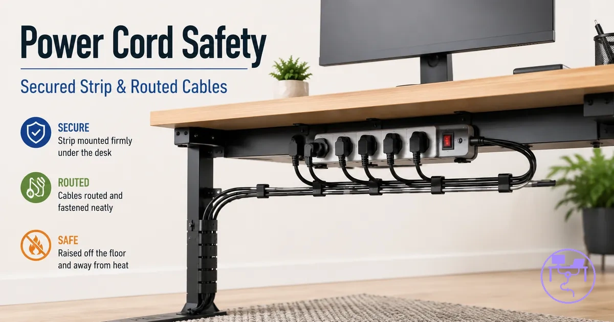
Safe desk cable management for power cords and power strips
Safe desk cable management for power cords and power strips is the practice of organizing and supporting powered connections within a desk cable management system so that power cords, adapters, chargers, power strips, and a surge protector remain accessible and properly supported under a desk. The goal is not only to reduce clutter but also to preserve conditions that may influence safe use, such as access, ventilation, cable support, and movement control. Safety outcomes depend on device load, mounting choices, desk design, and use conditions.
Common under-desk risk patterns often develop when power cords are left unsupported, when adapters crowd a confined area, or when power strips are mounted in positions that reduce clearance and visibility. Loose cable runs may create strain during desk movement, while compressed cable paths can make inspection more difficult. Heat, pressure, and restricted access can become concerns when powered components are grouped without considering operating conditions. A visually tidy setup is not necessarily the same as a safety-focused setup.
Safer layouts preserve access, airflow, support, and slack throughout the cable management setup. Power cords should remain reachable for inspection, power strips should maintain practical access, and under-desk cable support should avoid creating unnecessary pressure on cables or plugs. Mounting decisions, cable paths, and clearance around adapters can influence how the system performs over time. These conditions provide a basis for evaluating potential risks rather than relying on appearance alone.
The broader desk cable management system guide provides additional context for how powered and non-powered cable organization work together within a complete workspace layout. On this page, the focus remains on conditions such as ventilation, slack, mounting stability, desk movement, and access to connected devices. Understanding those conditions creates a clearer framework for assessing under-desk power cable arrangements before moving into more specific risk and support considerations.
What safe under-desk power cable management includes
Safe under-desk power cable management is the organization and support of powered connections within a desk cable management system to reduce avoidable risks while maintaining usable access to connected devices. It covers how power cords, adapters, chargers, power strips, surge protectors, and cable supports are positioned beneath a desk. Safety outcomes can depend on fit, device load, desk movement, mounting conditions, and user behavior.
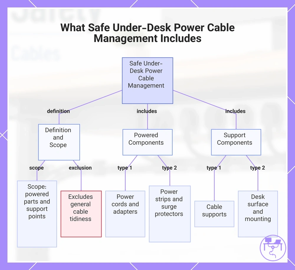
Safe under-desk power cable management includes more than keeping powered cables out of sight. The scope covers the condition of cable supports, the relationship between powered components and the desk surface, and whether access remains practical for inspection and operation. This definition applies to power cords, adapters, chargers, power strips, and surge protectors.
Before hardware is fixed in place, reviewing pre-installation safety checks can help confirm that fit, clearance, and support conditions are suitable for the intended under-desk power setup. The scope also includes how mounting, cord support, and movement may affect powered connections over time. Power safety focuses on powered components and their conditions, while general cable tidiness remains a separate concern.
Safe under-desk power cable management includes powered parts, support points, and access conditions such as:
- Power cords with appropriate slack to help reduce unnecessary strain during desk movement.
- Adapters and chargers positioned with usable access and sufficient clearance for their operating conditions.
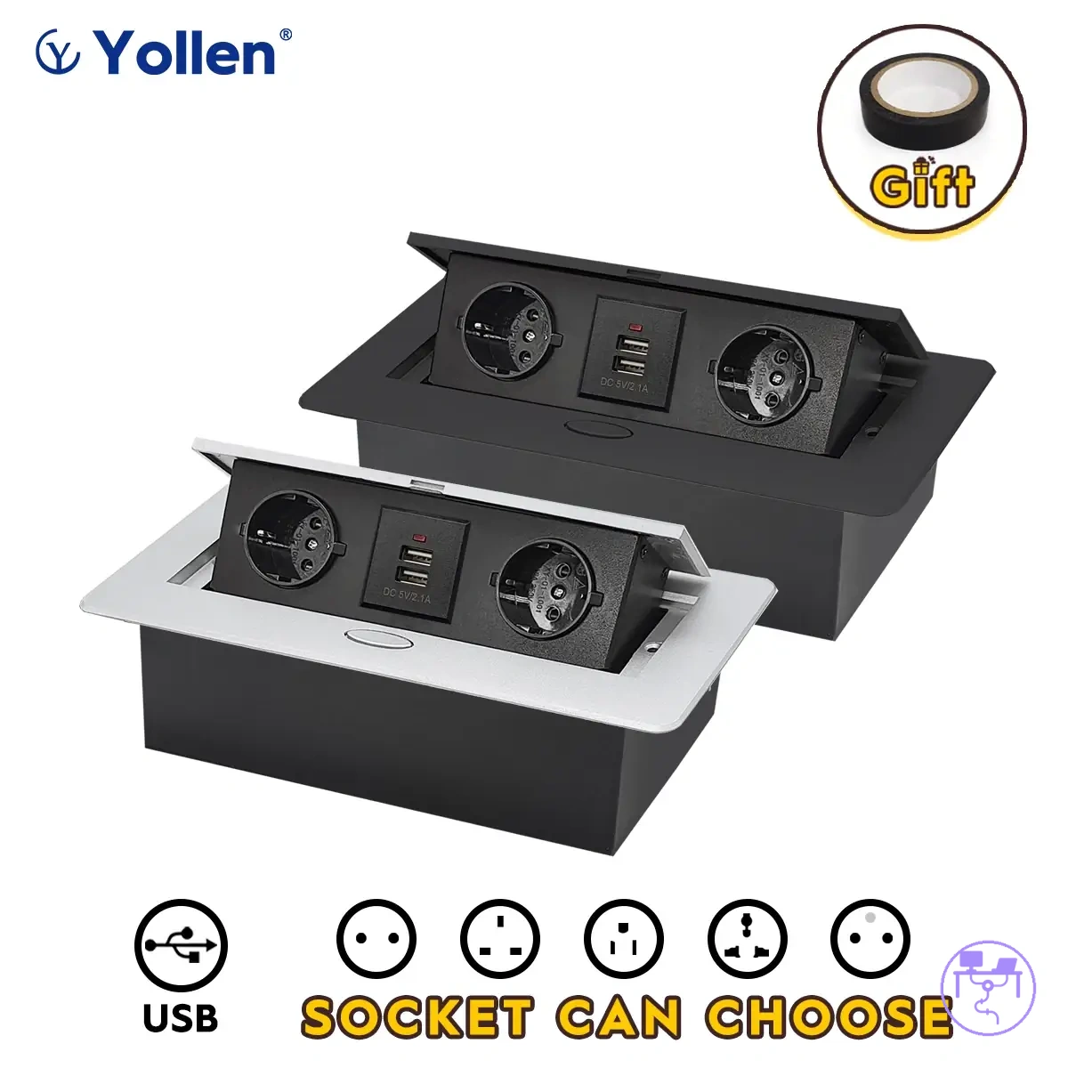
- Power strips and surge protectors placed so connections, ventilation areas, and switch access remain practical to reach.
- Cable supports that maintain cord support without creating excessive pressure on powered cables.
- Desk surface and mounting conditions that help keep powered components supported as intended.
This chart shows the definition, key powered components, and support elements of safe under-desk power cable management.
Power cords, adapters, chargers, and power strips inside the safety scope
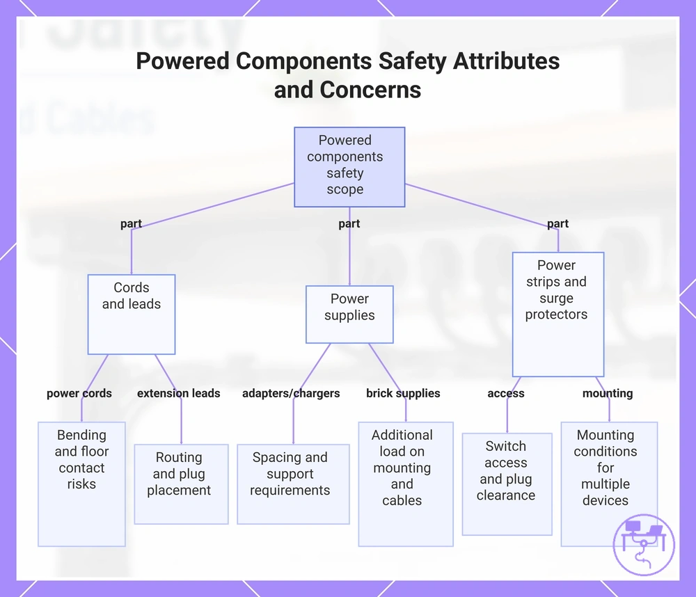
Powered components are the parts inside this safety scope because they carry, distribute, convert, or connect electrical power within an under-desk setup. Power cords, adapters, chargers, brick-style power supplies, extension leads, power strips, and surge protectors each introduce conditions that may affect access, support, heat, or cable strain depending on layout and use.
Each component changes safety attributes in a different way because powered parts vary in size, weight, connection style, and operating conditions. Heat, access, support, and strain concerns may change based on spacing, mounting, movement, and plug placement. The following component groups highlight the local conditions that matter most.
- Power cords can be affected by bending, strain, and floor contact, making routing and support important safety attributes.
- Adapters and chargers may require spacing and support because heat and cable weight can change local conditions.
- Brick-style power supplies, including larger power bricks, can place more load on mounting points or connected cables, affecting support requirements.
- Extension leads may influence cable routing and plug placement, making access and strain management relevant safety attributes.
- Power strips and surge protectors can affect switch access, plug clearance, and mounting conditions when multiple plug-in devices share one location.
This chart categorizes powered components by their type and highlights the key safety attributes—such as heat, access, support, and strain—that affect under-desk setups.
Cable hiding and general routing outside the power safety scope
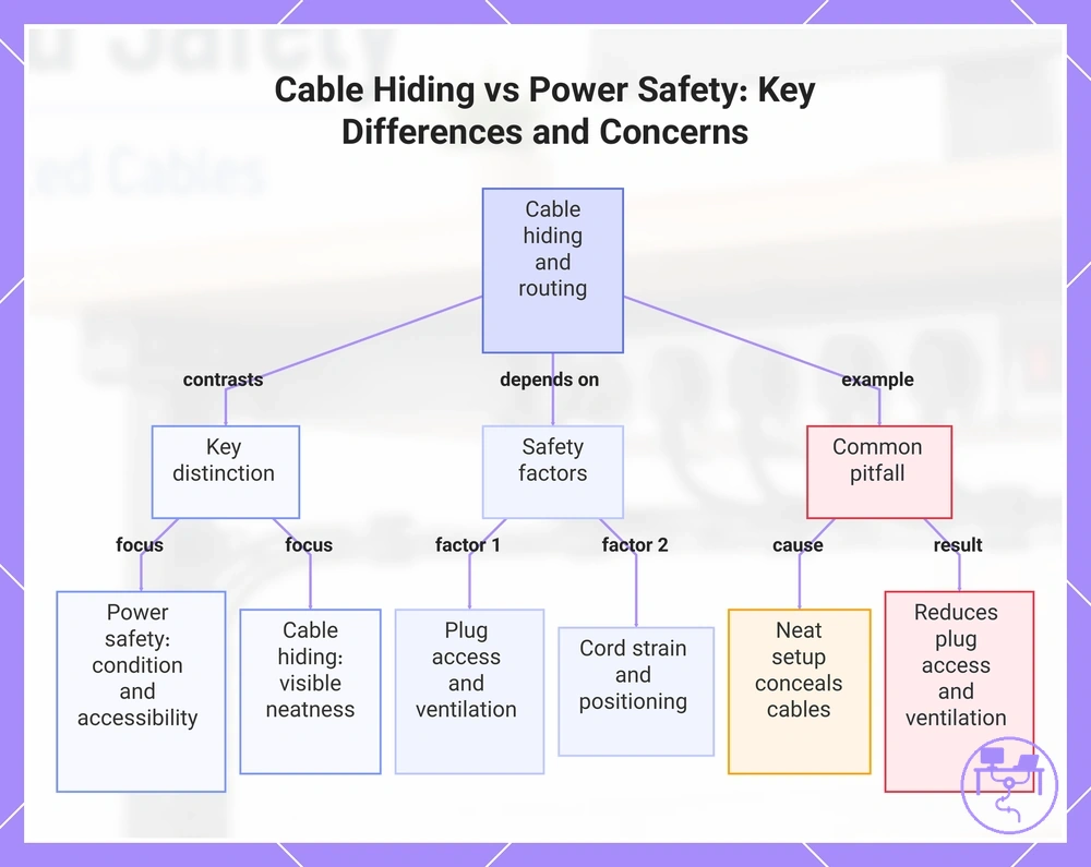
Cable hiding and general routing sit adjacent to the power safety scope, but hidden cables are not automatically safer powered cables. A tidy workspace may improve visible neatness through cable concealment, yet power-related conditions still depend on plug access, ventilation, cord strain, and how powered cables are positioned during normal use. In contrast, power safety focuses on the condition and accessibility of powered connections rather than their appearance.
A common problem occurs when a neat-looking setup conceals powered cables while reducing plug access, limiting ventilation, or increasing cord strain around a routing path. For broader guidance that falls outside this boundary, see route power cables correctly. Within this discussion, the key concerns remain plug access, ventilation, and cord strain rather than cable tidiness alone.
This chart explains the distinction between cable hiding and power safety, highlighting the true safety factors and the common pitfall of neat setups that compromise access and ventilation.
Electrical and physical risks in under-desk power layouts
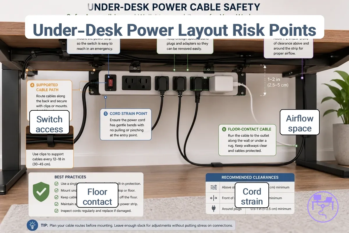
Electrical risks and physical risks in under-desk power layouts depend on layout conditions rather than cable presence alone. Heat, blocked ventilation, cord strain, sharp bends, loose floor contact, overloaded paths, and access obstruction may become concerns when powered components are crowded, unsupported, difficult to reach, or affected by movement. The effect of a condition can vary by load, desk movement, adapter placement, and user behavior.
Electrical conditions are often associated with heat buildup, blocked ventilation around adapters or a power strip, and restricted airflow in dense workstations. Physical movement conditions commonly involve cord strain, sharp bends, pressure points, or loose floor contact that may affect cable condition or plug stability over time. Access conditions form a separate risk category because access obstruction around a switch, outlet, or connection point can make inspection or emergency unplugging less practical. Adapter-heavy setups and movable desks may require additional attention because cable movement and component density can change these conditions.
Electrical and physical risks in under-desk power layouts depend on visible layout conditions, and the image below labels the conditions that the table organizes by risk type before later sections examine them in more detail.
| Risk category | Condition to check | Why it matters | Safer response |
|---|---|---|---|
| Electrical conditions | Heat, blocked ventilation, or crowded airflow around adapters and a power strip | Reduced airflow may increase heat concentration | Maintain clearance and airflow around powered components |
| Physical movement conditions | Cord strain, sharp bends, or pressure along a cable path | Repeated stress may affect cable condition over time | Use routing that reduces unnecessary tension and compression |
| Floor contact conditions | Loose cables with floor contact | May contribute to trip hazards or reduced plug stability | Keep cable paths supported and controlled |
| Access conditions | Access obstruction around switches, outlets, or plugs | Inspection and emergency unplugging may become less practical | Keep critical controls and connections reachable |
| Load path conditions | Overloaded paths created by concentrated powered connections | Higher component density may complicate monitoring and organization | Distribute powered connections according to the layout requirements |
The table summarizes common risk categories by condition, likely effect, and a more controlled response. The significance of any safety condition depends on the specific power layout and how it is used.
Heat buildup and blocked ventilation around power strips
Heat buildup and blocked ventilation around power strips can occur when airflow is restricted by the surrounding layout rather than by the power strip itself. Under a desk, enclosed trays, covered strips, stacked adapters, or crowded mounting areas may reduce airflow around power strips and power adapters. Improving spacing and keeping ventilation paths open can help reduce heat retention when component placement limits air movement.
Local conditions often determine whether blocked ventilation becomes a concern. Adapter crowding inside enclosed trays, fabric sleeves around powered components, dust accumulation, or blocked switch access can make inspection and airflow management more difficult. Heat buildup and blocked ventilation around power strips are checked through spacing, airflow, and access, so review the following conditions and check whether adequate spacing and switch access remain available.
- Enclosed trays: Inspect whether airflow around power strips and power adapters appears restricted.
- Stacked adapters: Check for adapter crowding that may limit spacing between powered components.
- Covered strip: Look for materials or objects that reduce open airflow around the power strip.
- Fabric sleeve and dust: Inspect whether sleeves, dust, or debris are collecting around powered components.
- Blocked switch areas: Check whether switch access remains clear and practical to reach.
Cord damage from tight bends, pressure, and sharp edges
Cord damage from tight bends, pressure, and sharp edges is often easier to prevent when the pressure point is identified before wear develops. Tight bends, compression, abrasion, and repeated contact with sharp edges can place stress on a power cord, especially when routing depends on limited space or unsupported cable paths. Adjusting the cable path to reduce concentrated force may help limit cord strain without treating neatness as a safety rule.
Risk depends on force, repetition, edge contact, and the condition of the cord jacket rather than on the presence of a bend alone. Tight bends around a small bend radius, pinch points near mounting hardware, clip pressure, cable ties tightened excessively, or hanging adapter weight can increase localized stress. Cord damage from tight bends, pressure, and sharp edges is easier to prevent when the pressure point is identified, so review the following cause-to-risk relationships.
- Tight bends: Visible sign: cord jacket distortion near a bend radius. Safer adjustment: use a wider cable path that reduces bend stress.
- Sharp edges and tray lips: Visible sign: edge wear or abrasion where the cord contacts a surface. Safer adjustment: reroute the cord away from repeated edge contact.
- Cable ties: Visible sign: compression marks on the cord jacket. Safer adjustment: allow enough space to avoid unnecessary compression.
- Clip pressure: Visible sign: flattened areas where the cord passes through a clip. Safer adjustment: use mounting methods that reduce concentrated pressure.
- Adapter weight: Visible sign: downward pull near a connector or support point. Safer adjustment: provide additional support so the cord carries less hanging weight.
Floor contact, loose cables, and trip hazards
Floor contact becomes a concern when loose power cords rest near chair paths, desk legs, or walking areas where accidental pulling can occur. Loose cables on or near the floor may create trip hazards and can affect plug stability when movement repeatedly shifts the cable position. The condition depends on how floor-level cords interact with people, furniture, pets, and equipment during normal use.
Movement is the main factor linking floor contact to plug stability. Chair wheels, foot contact, vacuuming, pets, movable desks, and dangling loops can change cable position and introduce angled tension at a plug connection. Floor contact, loose cables, and trip hazards are easiest to evaluate by identifying where movement or accidental pulling may occur, then checking whether plug stability remains consistent during routine use.
- Chair wheels: Repeated contact may shift floor-level cords and increase movement near plug connections.
- Foot contact: Accidental contact with loose power cords may create a physical hazard and introduce intermittent pulling.
- Vacuuming and pets: Unexpected cable movement may affect plug stability when cords remain exposed on the floor.
- Dangling loops: A cable loop may catch on movement paths or nearby objects, increasing the chance of accidental pulling.
- Movable desks and angled tension: Desk movement may place angled tension on a plug if cable position and desk movement do not remain aligned.
Power strip and surge protector mounting safety
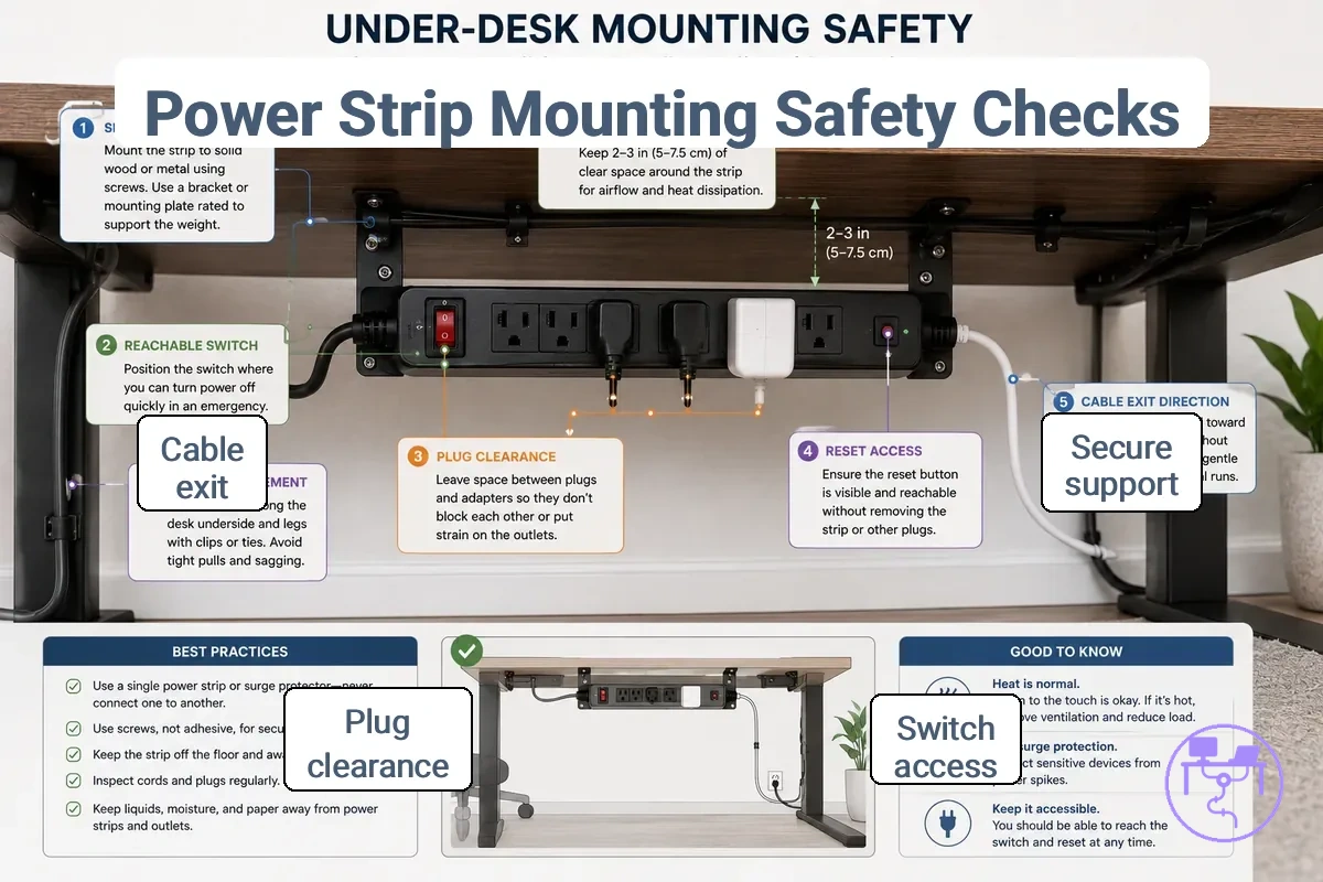
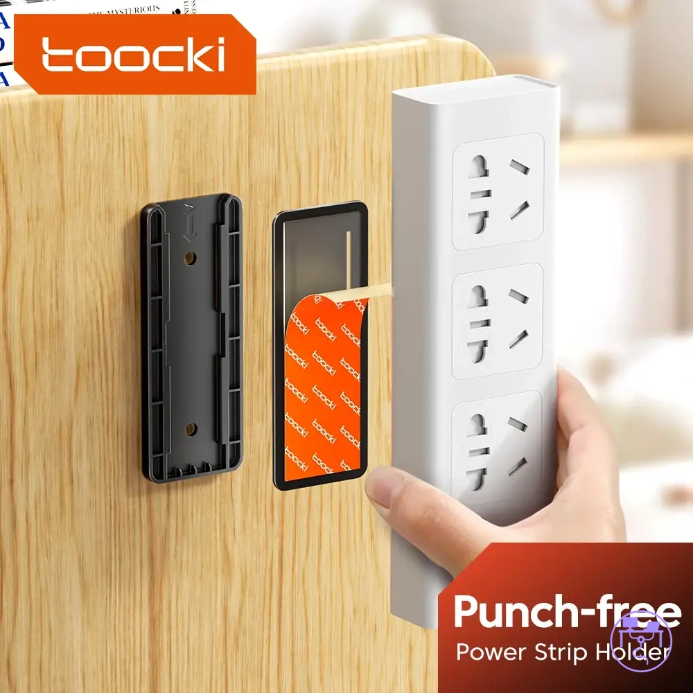
Power strip and surge protector mounting safety depends on whether the mounted position preserves support, access, and ventilation under the desk. Mounting can reduce loose floor contact, but it may create new strain or access problems if the holder, desk surface, or cable exit direction does not suit the setup. A mounted power strip is safer only when fit, load, movement, and user access remain controlled.
Mounting strength, surface fit, strip orientation, switch reachability, plug clearance, reset access, and cable exit direction all change how the under-desk mount performs. A screw, clamp, bracket, adhesive pad, strip holder, or surge protector holder may behave differently depending on desk material and the weight of connected cables. Power strip and surge protector mounting safety is easier to judge when the layout labels support, access, and ventilation conditions before the checklist.
For height-changing or frequently adjusted desks, standing desk cable movement safety should be part of the mounting criteria because desk movement can add slack, strain, or cable exit direction changes. A mounted position may be suitable for a fixed desk but less suitable when the desk moves often or when cable length does not move with the work surface.
- Support: Check whether the power strip or surge protector holder matches the mounting surface and connected cable weight.
- Access: Keep switch reachability, reset access, and plug removal practical after mounting.
- Ventilation: Maintain open space around the mounted power strip so airflow is not blocked by the holder or nearby objects.
- Plug clearance: Confirm that plugs, adapters, and cable exits are not compressed by the mounting position.
- Movement: Allow enough slack and a suitable cable exit direction when desk movement or frequent adjustment may add strain.
Screw, clamp, bracket, and adhesive mounting conditions
Screw mounting, clamp mounting, bracket mounting, and adhesive mounting conditions differ in suitability because mount suitability depends on desk surface, load weight, and removability requirements. A mounting method that suits one desk material may be less suitable on another when underside clearance, surface condition, or cable load changes. Each support method changes strength, removability, and surface requirements, so selection depends on local installation conditions rather than a universal mount preference.
Desk material, underside clearance, load weight, adhesive surface quality, screw depth, clamp pressure, and bracket alignment all influence mounting performance. Clamp mounting may depend on available clearance and contact pressure, while adhesive mounting can depend on surface quality and load weight because attachment conditions vary. Screw mounting and bracket mounting may offer different trade-offs for support and removability, but neither approach is suitable for every desk or holder configuration.
Screw, clamp, bracket, and adhesive mounting conditions differ by support strength and desk surface, as summarized below.
| Mount type | Surface condition | Strength trade-off | Caution |
|---|---|---|---|
| Screw mounting | Depends on desk material and screw depth | May provide stronger support when surface conditions are suitable | Surface compatibility varies by desk construction |
| Clamp mounting | Requires adequate underside clearance | Usually offers higher removability | Clamp pressure may not suit every desk edge |
| Bracket mounting | Depends on bracket alignment and strip support | Can improve mounting stability when properly aligned | Misalignment may affect strip positioning and access |
| Adhesive mounting | Depends on adhesive surface quality | Performance may vary with load weight and surface condition | Adhesive attachment may not suit every mounting environment |
Outlet access, switch access, and plug clearance
Outlet access, switch access, and plug clearance depend on whether mounted power hardware remains reachable after installation. A mounted power strip or surge protector should preserve outlet access, switch access, and plug removal because a position that limits reachability may make inspection, adjustment, or emergency unplugging less practical. The condition depends on clearance space, cable routing, connected adapters, and the mounted location.
Clearance conditions are easiest to assess by looking at visible access around the connected hardware. Plug clearance, adapter clearance, cable bend direction, switch visibility, reset button reachability, and outlet spacing can change when plugs occupy adjacent outlets or when cable paths restrict movement around the mounted unit. Outlet access, switch access, and plug clearance are verified before the mounted position is considered safe, so a practical access check should confirm that each control and connection remains reachable without obstruction.
- Confirm that outlet access remains available around connected plugs and adapters.
- Check that plug removal can be completed without moving unrelated cables or devices.
- Verify that switch access remains clear and that the reachable switch is visible.
- Ensure that the reset button on a surge protector can be reached when needed.
- Review adapter clearance and outlet spacing to confirm that larger adapters do not block adjacent connections.
- Check that cable bend direction does not restrict plug movement or connection access.
- Confirm that emergency unplugging remains practical without navigating around obstructions.
Cable trays, sleeves, clips, and baskets for safer power cord support
Cable trays, sleeves, clips, and baskets for safer power cord support are cable organizer parts that manage how power cords are carried, positioned, and monitored within a desk cable management system. Their safety function depends on how they handle cable load, movement, visibility, and spacing rather than on appearance alone. A cable tray, sleeve, clip, basket, holder, tie, or channel may perform differently when cable density, movement, or load conditions change.
Ventilation, load, compression, and access are the main criteria for evaluating power cord support parts. Cable trays and wire baskets differ in airflow and visibility, while sleeves, clips, ties, and channels can influence compression levels, bend direction, or inspection access depending on how cables are grouped. These attributes matter because powered cables may require different clearance and monitoring conditions than low-voltage signal cables.
Cable trays, sleeves, clips, and baskets for safer power cord support differ by ventilation, load, compression, and access, and the image below compares visible support conditions that affect power cord management.
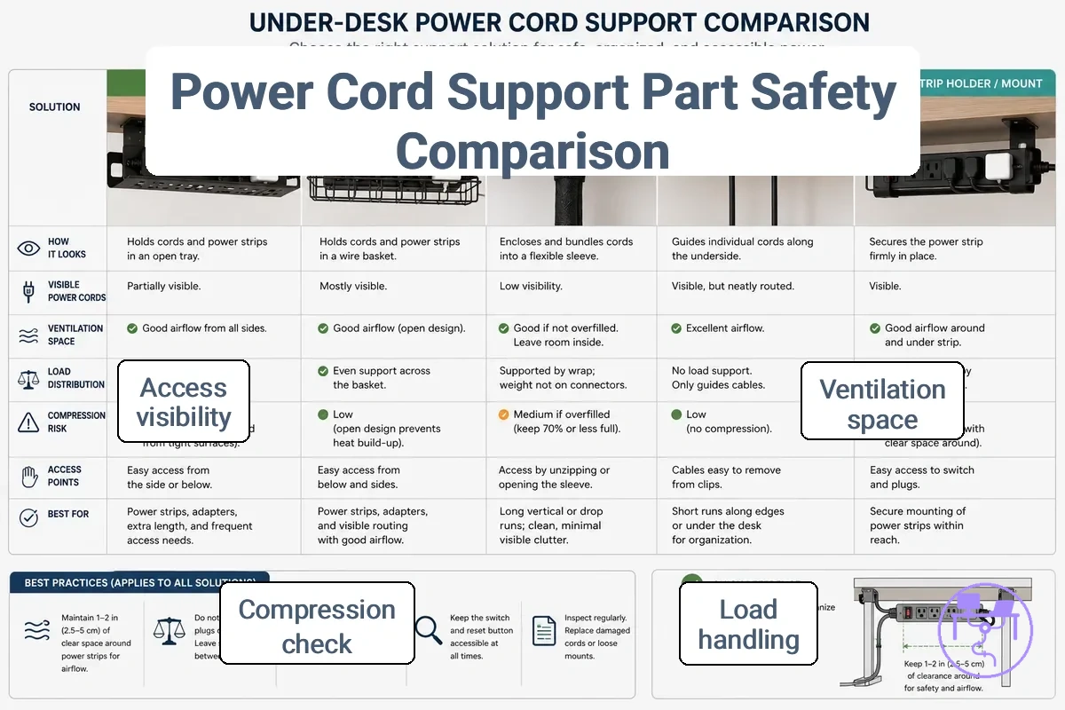
The table compares common organizer parts through part-to-attribute evaluation. A visually neat cable support arrangement is not automatically suitable for powered cables if ventilation, compression, load handling, or inspection access becomes limited.
| Part | Safety attribute | Condition to check | Effect or decision |
|---|---|---|---|
| Cable trays | Load handling and access | Weight distribution and inspection visibility | May suit grouped power cords when access remains practical |
| Sleeves | Compression and ventilation | Fill level, compression, and airflow around enclosed cables | May require review when cable density limits airflow |
| Clips | Grip and bend direction | Pressure on the cable path and routing angle | Can help maintain routing when pressure remains controlled |
| Baskets | Airflow and cable weight | Visibility, airflow, and accumulated cable load | May improve cable organization while preserving open airflow |
| Holders | Cable position control | Cord stability and reachability | Can help keep specific power cords available for inspection |
| Ties | Compression management | Tightness around grouped cables | Excessive compression may reduce routing flexibility |
| Channels | Routing containment | Available space and cable access | May improve routing control when access remains available |
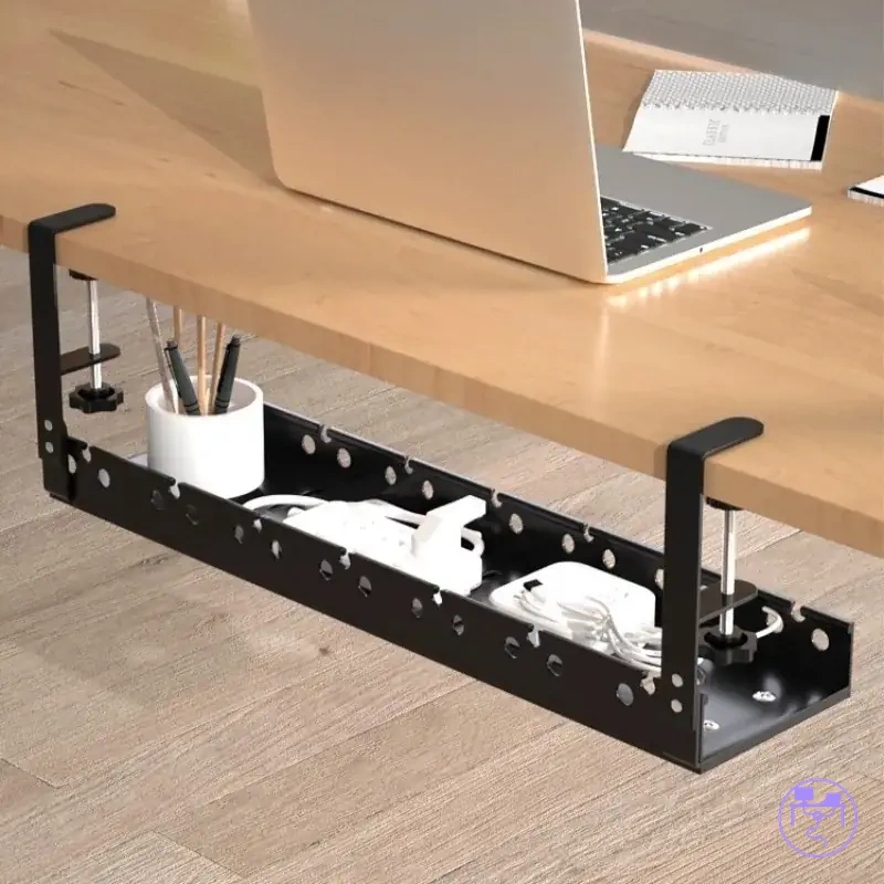
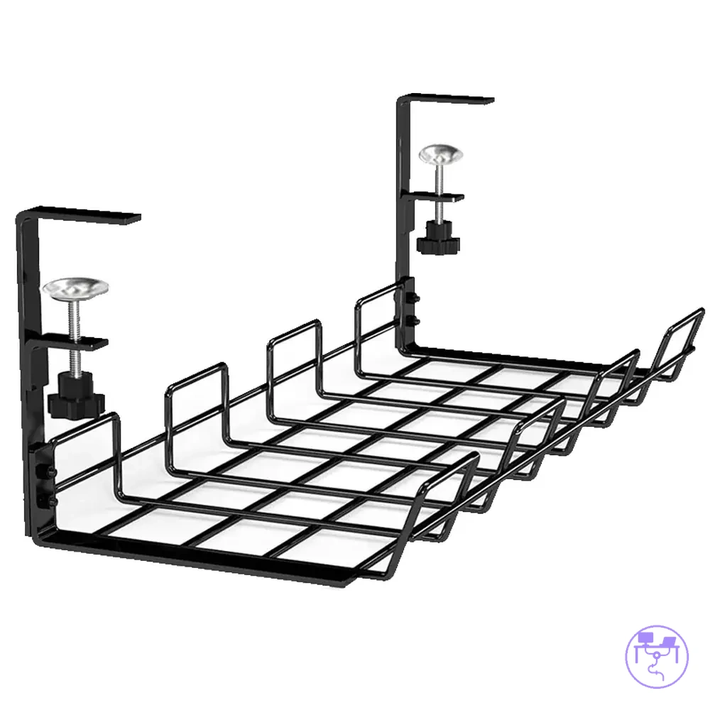
Open trays and wire baskets for ventilation and load support
Open trays and wire baskets can help when ventilation and load visibility are important criteria for managing power cables. Open trays and under-desk wire baskets make cable weight, plug visibility, and adapter spacing easier to inspect because cables remain visible during normal use. Their suitability depends on cable load, movement, and how the support method fits the powered components being carried.
Open trays and wire baskets are judged by ventilation and load visibility because airflow, cable weight distribution, and access to switches or outlets can be checked directly. Tray depth, material rigidity, adapter spacing, and cable arrangement may influence how well an open cable tray or wire basket performs in a specific installation. Open designs can be useful when these conditions remain visible and manageable, but fit and cable load still determine whether the support method suits the application.
- Airflow is easier to observe when open trays leave ventilation paths visible.
- Cable weight is easier to evaluate when wire baskets provide clear load visibility across the cable run.
- Plug visibility can improve when connectors remain exposed rather than enclosed.
- Adapter spacing is easier to inspect when adjacent adapters are not crowded by the support layout.
- Tray depth and material rigidity should match the cable load so cords remain contained and reachable.
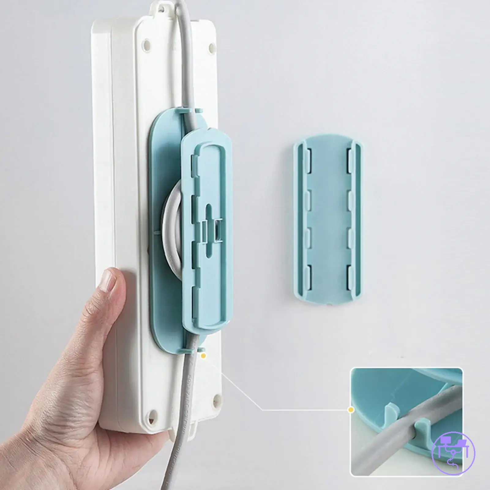
Cable sleeves and clips for protection without compression
Cable sleeves and clips protect power cords only when they guide without compression, because compression is the main local risk that can pinch a cord path or trap heat around grouped cables. A cable sleeve or cord clip can help organize routing when sleeve fill level, clip spacing, cord thickness, and adapter exits leave enough room for the cable to follow its natural path rather than being forced into a confined position.
Cable sleeves and clips have limits because protection depends on fit, pressure, and movement conditions. Sleeve fill level that becomes too dense may increase compression or trap heat, while clip spacing, bend direction, adhesive reliability, and cord thickness can influence how much pressure reaches the cable surface. Cable sleeves are not suitable for every power cord arrangement, and movement tolerance should be considered wherever cables, adapters, or connected equipment move during normal use.
| Do | Don't |
|---|---|
| Use clip spacing that guides the cable path | Create pinch points with closely spaced clips |
| Maintain a sleeve fill level that leaves room for cables | Overfill a cable sleeve until cables are compressed |
| Allow a natural bend direction near adapter exits | Force cables into sharp routing changes |
| Check adhesive reliability where movement occurs | Rely on unsupported clips in high-movement areas |
| Match routing to cord thickness and movement tolerance | Assume one sleeve or clip arrangement suits every cable |
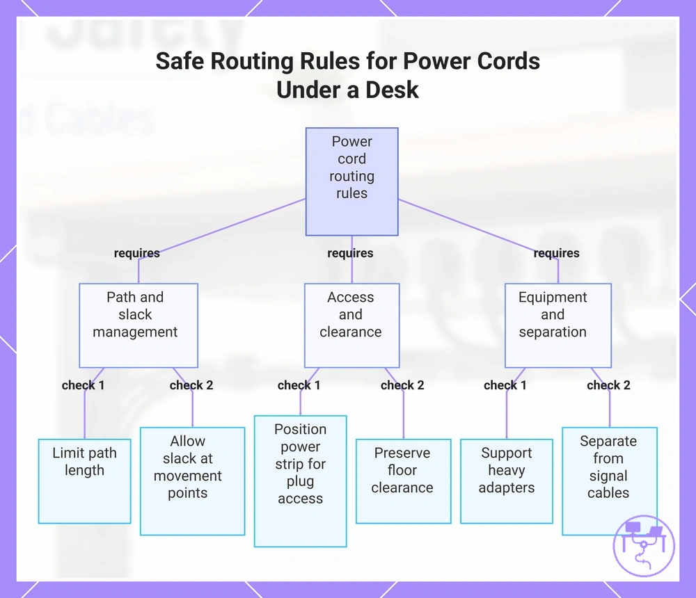
Safe routing rules for power cords under a desk
Safe routing rules for power cords under a desk organize the route by strain, access, separation, and slack. Power cords should follow a cord path that limits unnecessary tension while preserving plug access and floor clearance, because routing conditions may change when cable load, connected equipment, or desk movement affects the under-desk route.
Power cable routing depends on local conditions rather than a fixed layout pattern. Path length, power-strip position, adapter weight, signal-cable crowding, and available slack can influence how a cable path behaves during normal use. The goal is to manage these conditions without turning routing into a full installation process or a cable-hiding project.
The following steps provide a practical usage method for routing power cords while keeping inspection possible. In some situations, a route that remains partly visible may be more useful than a completely concealed route because plug access, cable condition, and movement points remain easier to inspect.
- Choose a cord path with only the required path length, because excess cable may create additional strain points and unnecessary movement.
- Allow slack where desk movement occurs, because a route that becomes tight during adjustment may increase tension on power cords.
- Position the power strip where plug access remains practical, because inspection and disconnection may become more difficult when connections are obstructed.
- Support heavier adapters when adapter weight affects the connection area, because unsupported weight may increase localized strain near plugs.
- Maintain separation from dense signal-cable crowding when possible, because a clearer route can improve cable identification and inspection.
- Preserve floor clearance along movement paths, because loose power cords near the floor may be affected by foot traffic, chair movement, or accidental pulling.
This chart shows the key checks for managing power cord routing under a desk, covering path planning, access, and equipment separation.
Separating power cords from crowded signal cable bundles
Separating power cords from crowded signal cable bundles helps improve access, reduce crowding, limit unnecessary strain, and simplify identification. When power cords, monitor cables, USB cables, and charging cables are grouped too closely, inspection and cable tracing may become more difficult, especially when movement, adapter weight, or shared trays change the cable arrangement over time.
Separating power cords from signal cable bundles should not be treated as a guaranteed interference fix or a performance boost. The practical goal is easier access, clearer identification, and reduced cable crowding under local routing conditions. A practical cable grouping rule is to keep power cords organized as a distinct group when shared trays, sleeves, ties, or power bricks make a mixed cable bundle harder to inspect.
- Separate power cords from dense monitor cables when cable identification becomes difficult, because clearer grouping can improve tracing and inspection.
- Use power-signal separation when USB cables and charging cables create cable crowding, because access to individual connections may become easier.
- Review shared trays that contain power bricks and signal cables together when routing changes occur, because concentrated weight may increase localized strain.
- Adjust ties and sleeves when a mixed cable bundle becomes difficult to follow, because distinct grouping can improve identification and access.
Leaving slack for adapters, plugs, and desk movement
Leaving slack for adapters, plugs, and desk movement helps reduce strain when cable movement might otherwise pull on connections. The balance is between providing enough slack for movement and maintaining control so loose loops do not create additional hazards. Slack can help preserve plug angle, reduce stress from adapter weight, and create a strain relief point when the cable path changes during normal use.
Desk movement should be considered only where it affects power-cord behavior. Sit-stand travel, chair movement, floor-to-desk runs, cable clips, and cable length can change how much movement allowance is appropriate, but the amount of cable slack depends on the route and connected equipment. A suitable slack arrangement should allow movement without creating loose loops, and requirements may vary with desk travel and cable length.
- When plug angle changes during use, leave enough slack to reduce pulling at the connection point.
- When adapter weight affects plugs or connectors, use a strain relief point so cable slack can reduce localized load.
- When sit-stand travel changes cable position, allow movement allowance so the cable path can move without becoming tight.
- When floor-to-desk runs cross movement areas, keep cable slack controlled with cable clips to avoid loose loops.
- When chair movement regularly affects nearby cables, review slack and cable length together so movement does not increase strain.
Choosing a power cord organizer for a safe desk setup
Choosing a power cord organizer for a safe desk setup depends on matching organizer attributes to the actual powered layout. A power cord organizer should be selected according to load, mounting, ventilation, access, and movement conditions because a holder type, tray, sleeve, or clip may perform differently when cable weight, desk fit, or user movement changes.
The main criteria are load handling, mounting method, ventilation, and power strip access. Tray capacity should match the amount of cable and connected equipment being supported, while sleeve fill should leave enough room to avoid unnecessary compression. Clip grip and material strength should suit the cable path and movement conditions. Desk fit also matters because mounting options may vary with desk surfaces, clearance, and available attachment points.
The table below compares organizer attributes through safety conditions rather than product categories. A power cable organizer that performs well for one setup may involve trade-offs in another if movement, access requirements, or mounting conditions differ.
| Safety condition | Organizer attribute | What to check | Decision signal |
|---|---|---|---|
| Higher cable load | Tray capacity | Cable weight and supported equipment | Choose capacity that matches the expected load |
| Limited mounting options | Mounting method | Desk surface and attachment points | Select a method that suits desk fit |
| Grouped cable routing | Sleeve fill | Available internal space and compression | Prefer fill levels that preserve cable flexibility |
| Frequent cable movement | Clip grip | Routing stability and movement allowance | Use grip strength appropriate for the cable path |
| Power strip management | Holder type and power strip access | Plug clearance and switch reachability | Maintain practical access after installation |
| Long-term durability needs | Material strength | Load, movement, and mounting conditions | Match material characteristics to expected use |
| Ventilation concerns | Organizer design | Airflow around grouped cables | Prefer layouts that keep inspection and airflow practical |
These criteria help choose a safe setup by keeping the selection process focused on conditions rather than product labels. A cord organizer should be evaluated through trade-offs between load, mounting, ventilation, access, movement, and desk fit before any specific organizer type is considered.
The products below are useful examples for comparing available options. Before buying, check that the compatibility criteria, key features, and product details match your needs.
Load capacity, mounting strength, and material fit
Load capacity, mounting strength, and material fit determine whether an organizer can support the powered layout safely. A tray, holder, clamp, screw mount, or adhesive mount should be narrowed by desk material, strip size, adapter weight, and expected cable load because support conditions can change when powered components add weight or heat exposure to the setup.
Holder weight rating and load rating can help compare organizer options, but ratings do not remove the need for user checks. Mounting strength may depend on screw or clamp support, adhesive limits, desk material, and material rigidity, while material fit may change when the organizer sits near warm adapters or crowded powered cables. The final check should confirm that the selected organizer still holds the actual layout securely and remains practical to inspect during use.
- Match load capacity to strip size, adapter weight, and grouped cable weight so the organizer is not selected below the powered layout’s support needs.
- Check mounting strength against the actual mounting method, because screw, clamp, and adhesive support can vary by surface and installation condition.
- Compare material fit with desk material, clearance, and attachment points so the organizer suits the local desk structure.
- Review adhesive limits when the organizer carries a power strip or heavier adapters, because adhesive performance may vary by surface quality and load.
- Assess material rigidity near heat exposure conditions so trays or holders do not flex, crowd, or shift around powered components.
When a dedicated holder is safer than a general cable tray
When a dedicated holder is safer than a general cable tray depends on support, access, ventilation, and plug clearance. A dedicated holder is safer only when it better preserves support and access for the power strip, because holder grip can help maintain strip orientation and make plug removal more predictable under the desk. A general cable tray may be equally suitable when tray openness, cable load, and access conditions keep the power strip stable and reachable.
Fit conditions determine which option better matches the actual layout. Adapter spacing, under-desk movement, cable load, strip orientation, and ventilation can change how a power strip holder or general cable tray performs after installation. Either option can be safer when it fits the actual power layout and maintains the conditions needed for inspection and use.
| Option | Better when | Safety trade-off | Watch point |
|---|---|---|---|
| Dedicated holder | Holder grip keeps the power strip secure and accessible | May improve strip orientation and plug removal | Check adapter spacing and holder fit |
| General cable tray | Tray openness supports the cable load while preserving ventilation | May provide more flexibility for changing cable layouts | Review plug clearance and under-desk movement |
Safety checks after setup and during use
Safety checks after setup and during use confirm whether the installed setup still matches safety conditions. These checks do not guarantee future outcomes because cable load, movement, device changes, and mounting conditions may change over time. The goal is to verify that heat, strain, access, support, and movement conditions remain consistent with the original setup.
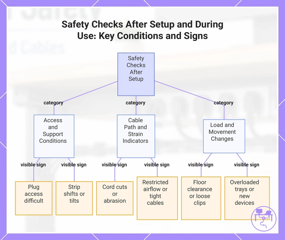
Safety checks after setup and during use verify heat, strain, access, support, and movement conditions through visible signs. A follow-up check should focus on whether plug access remains practical, whether strip stability has changed, and whether cables still follow the intended route. The checklist below links each condition to a visible sign and its possible meaning.
- Plug access: If plugs or switches become difficult to reach, access conditions may no longer match the original layout.
- Strip stability: If the power strip shifts, tilts, or moves during normal use, support conditions may require review.
- Cord damage: If cuts, abrasion, flattening, or unusual wear appear, the cable path may be creating excessive strain.
- Ventilation: If airflow around grouped cables becomes restricted, heat conditions may have changed.
- Slack: If cables become tight during movement, the available slack may no longer match the route.
- Floor clearance: If cables begin to hang near walking or chair paths, movement conditions may increase pulling risk.
- Loose clips: If clips no longer hold cables consistently, routing stability may be reduced.
- Overloaded trays: If tray contents increase noticeably, cable load may exceed the original support assumptions.
- Changed device loads: If new devices, adapters, or power strips are added, earlier load and support decisions may need review.
Changed device loads and movement can affect earlier decisions because additional adapters, new equipment, or altered desk positions may change cable weight, routing behavior, and support conditions. A safety review is most useful when it compares the current layout with the conditions that existed when the setup was first organized.
maintenance and adjustment can help keep the setup aligned with changing conditions after installation. Ongoing checks and small adjustments may be more useful than waiting for visible problems to accumulate before reviewing the layout.
The products below are useful examples for comparing available options. Before buying, check that the compatibility criteria, key features, and product details match your needs.
This chart shows the main conditions to verify during safety checks after setup, linking each condition to visible signs that may indicate a problem.