Desk cable management system parts and how they work
Desk cable management system parts are physical components that organize cables by holding, routing, covering, grouping, or supporting them around a workstation. These parts define how a cable route behaves under-desk, across a desktop opening, or near a power point. Their main purpose is cable control, not product shopping.
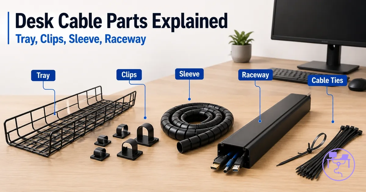
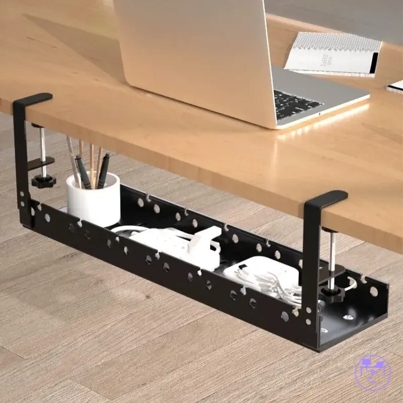
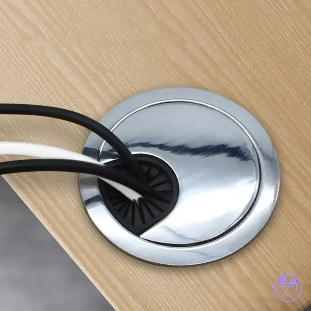
Desk cable management system parts can be separate items or combined inside one wider system. The image for this page should label how desk cable management system parts hold, route, cover, group, and support cables across one organized cable route.
The part-function overview below groups cable organizer parts by what they change: support, concealment, access, fit, or control. For the broader page context, see the desk cable management system guide.
A cable tray or J channel can support a cable bundle under-desk, while a raceway or sleeve can reduce visible cable exposure. Clips, ties, and mounts create control points for slack and direction. A grommet guides cables through a desktop opening, and a power strip holder supports heavier power-related items when its load rating, ventilation, and access conditions fit the setup.
| Part group | Main function | Typical condition | Effect on cable setup |
|---|---|---|---|
| Cable tray or J channel | Supports cables under the desk | Cable bundle needs load support and access | May reduce dangling and keep the route easier to reach |
| Raceway or sleeve | Covers or groups visible cables | Visibility, concealment, and access need balance | Can make the cable route cleaner while changing maintenance access |
| Clips, ties, and mounts | Create local control points | Slack, surface type, and adjustability matter | Can position wires and keep small bundles directed |
| Grommet or pass-through | Guides desktop cable entry | Cables move from the work surface to the underside route | Can reduce edge rubbing and make the entry point clearer |
| Power strip holder | Supports power strips or adapters | Load rating, ventilation, and plug access must be checked | May improve stability and service access when the holder fits the setup |
These part categories prepare the page for a clearer definition of what counts as a desk cable management system part. Each component should be read by its function, condition, and effect on the cable route before any later choice, fit, or installation detail is considered.
What counts as a desk cable management system part
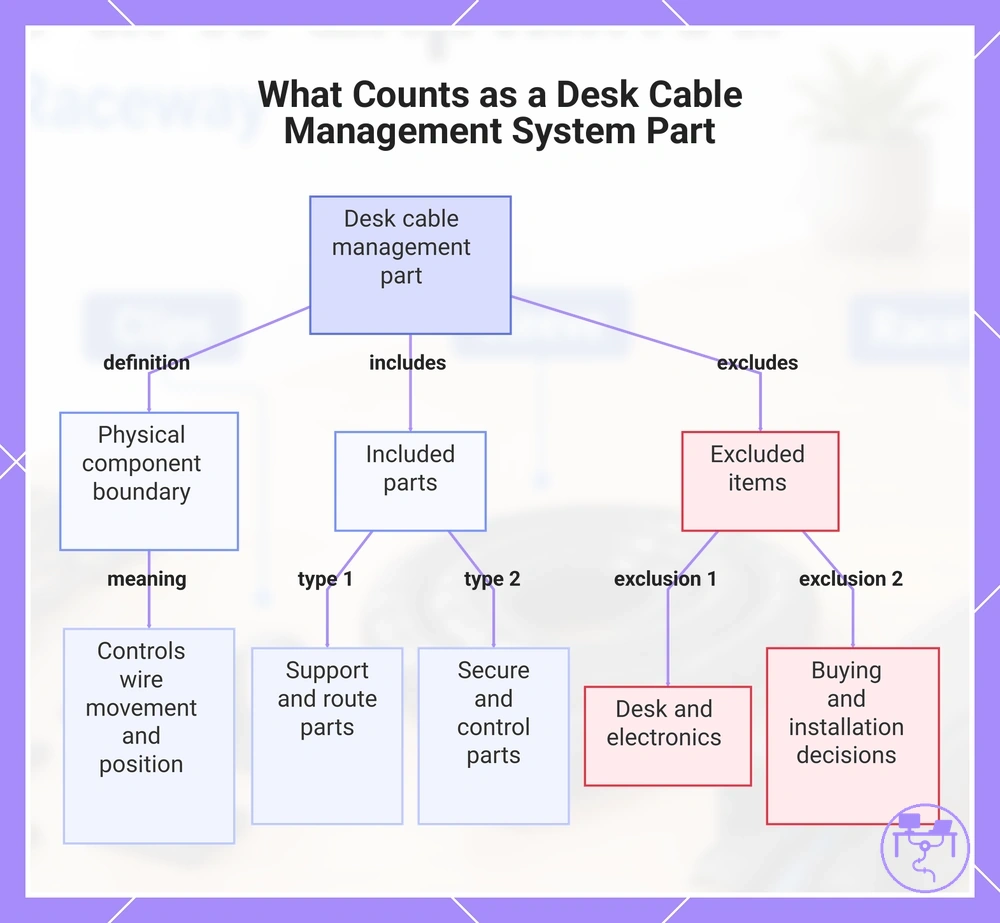
A desk cable management system part is a physical component used to support, route, conceal, group, or secure desk cables. The part belongs inside the cable path when it directly controls how wires move, rest, pass through, or stay positioned around the desk. This keeps the definition limited to a physical component boundary.
Included parts can be a tray, channel, sleeve, clip, tie, grommet, mount, or power support accessory. A tray or channel supports or directs a cable path, while a sleeve can group cables and reduce visible exposure. A clip, tie, or mount creates a control point, and a grommet or pass-through qualifies when it guides desktop entry through a cable opening.
- Inside scope: trays, channels, sleeves, clips, ties, grommets, mounts, and power support parts that control cables.
- Inside scope: a standalone part that handles one cable-control function.
- Inside scope: a combined component when it is part of a wider desk cable management system.
- Outside scope: the desk, monitor, computer, charger, or connected electronics themselves.
- Outside scope: full buying choice, product ranking, and installation process decisions.
A cable management part is not the same as the entire desk setup or the equipment connected to the cables. This section defines what belongs in the parts scope; later sections can handle comparison, fit, and installation order without changing the definition.
This chart defines a desk cable management system part and clarifies which components are included and excluded from the scope.
Main part groups in a desk cable management system
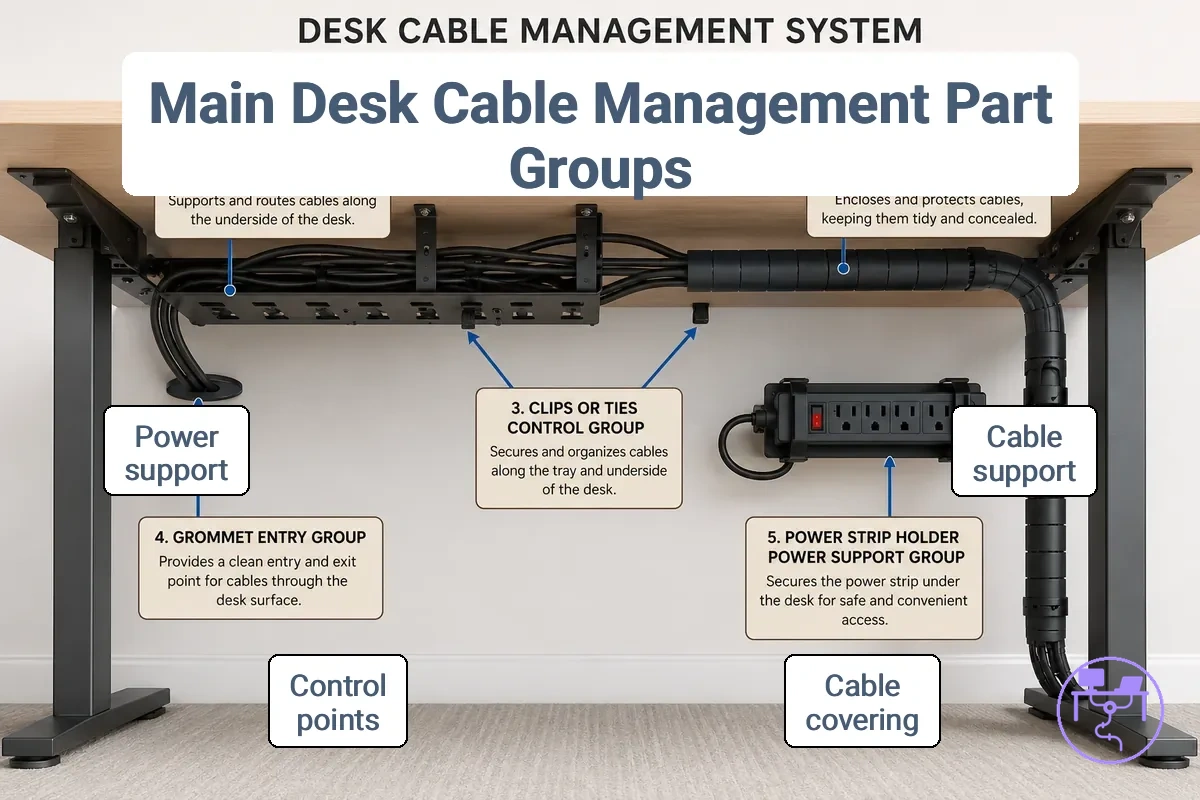
Part groups in a desk cable management system are best understood by function because each group controls a different part of the cable route. Functional groups classify how cables are supported, covered, directed, entered through a surface, or connected to power support. The main categories are support, concealment, control, entry, and power support.
Main part groups in a desk cable management system can be organized by what each group controls. The diagram labels the major component families and shows how they relate to cable movement, visibility, access, and positioning.
| Part group | What it controls | Common condition | Practical effect |
|---|---|---|---|
| Cable tray or J channel | Support for a cable bundle | Multiple cables need under-desk support | May reduce dangling when load is distributed appropriately |
| Raceway or sleeve | Concealment and cable grouping | Cables move through a visible area | Can create cleaner cable runs while maintaining a cable route |
| Clips and ties | Control point positioning | Individual wires require direction or slack management | Can help reduce excess slack and improve wire positioning |
| Grommet or pass-through | Desktop entry and cable direction | Cables pass through a cable opening | Can guide cables between the desktop and under-desk area |
| Power strip holder | Power support and placement | Power accessories need a dedicated location | May improve access and organization depending on the setup |
These part groups work together rather than competing with each other. A cable tray or J channel may provide support, while a raceway or sleeve manages concealment. Clips and ties create a control point along the cable route, and a grommet manages the transition through the desktop. A power strip holder supports the power section of the cable path.
A simple cable route may begin at a desktop entry point, continue through clips or ties, pass into a sleeve or raceway, and finish at a supported cable bundle. This functional classification connects naturally to broader desk cable management system types without turning the section into a comparison page.
Cable trays and J channels for under-desk support
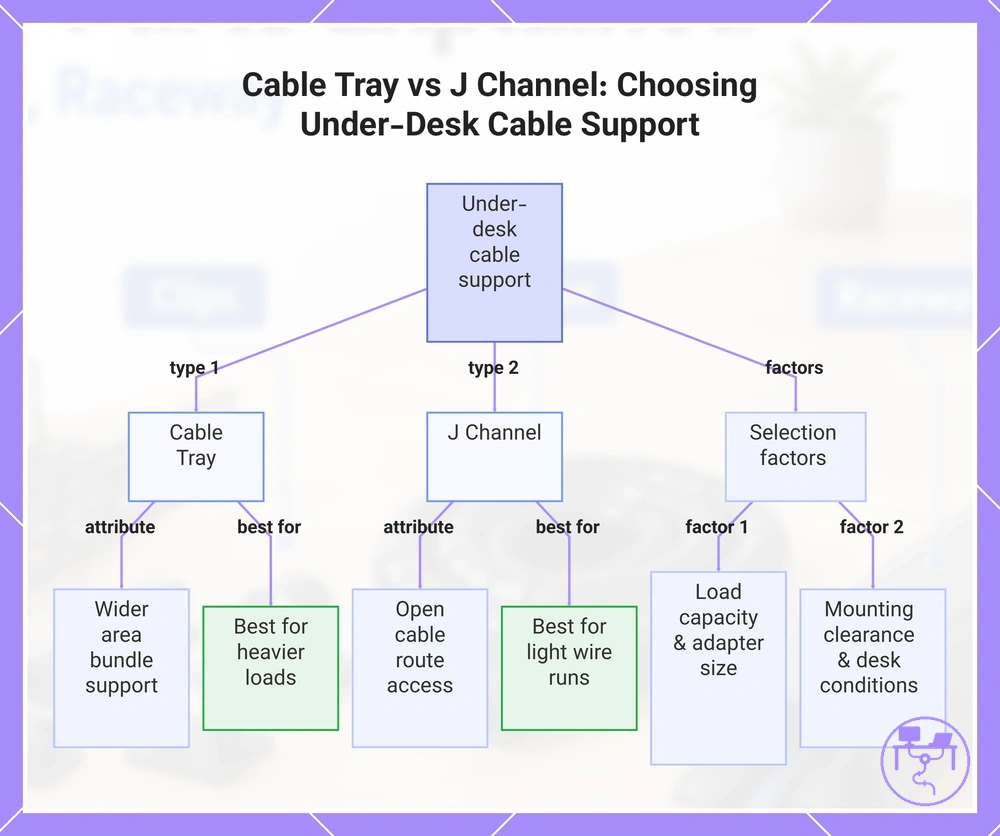
Cable trays and J channels are under-desk support parts that hold and organize cables below the work surface. A cable tray typically supports a cable bundle across a wider area, while a J channel provides more open access to the cable route. Both serve the core purpose of under-desk support and sag control.
- Support capacity: suitability depends on cable bundle size, adapter presence, and rated load.
- Openness: a J channel often leaves more of the cable route visible for access and adjustment.
- Mounting position: available clearance and desk conditions can influence support suitability.
- Access: easier access may help when cables or adapters need repositioning.
A cable tray can support a larger cable bundle when the load remains within its intended capacity, while a J channel may prioritize open access and visibility. Load, adapter size, mounting position, and clearance all affect support performance. For example, a light wire run may fit comfortably in a J channel, while a heavier under-desk bundle may benefit from a wider cable tray that distributes support across a larger area.
This chart compares the two main types of under-desk cable supports and helps select the right one based on cable load, access needs, and mounting conditions.
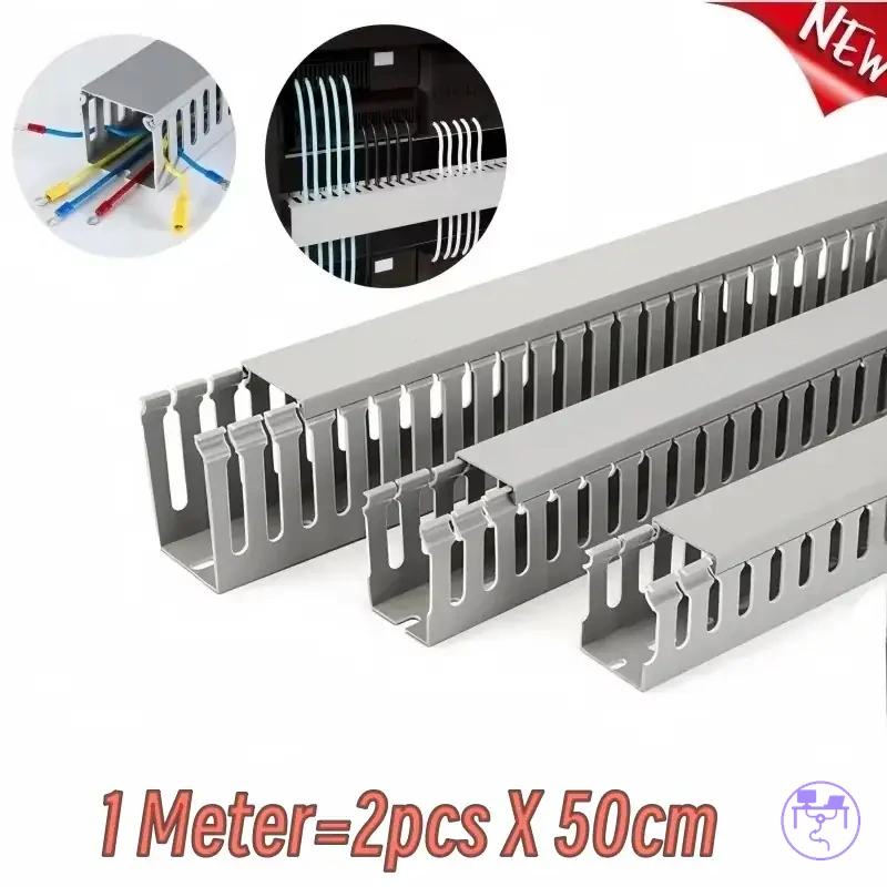
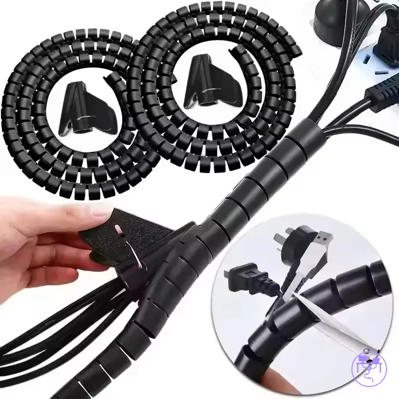
Raceway channels and sleeves for cable covering
Raceway channels and cable sleeves cover or group visible cables to reduce visible cable exposure along a cable route. A raceway channel uses a more defined enclosure, while a cable sleeve groups cables inside a flexible covering. Both support concealment, but the balance between access and concealment depends on the cable route and bundle condition.
| Raceway channels | Cable sleeves |
|---|---|
| More enclosed covering | Flexible cable grouping |
| Lower flexibility | Higher flexibility |
| Access depends on enclosure design | Access depends on bundle density |
| Often used along a desk edge or wall-adjacent route | Often used around a cable bundle |
A raceway channel covers cables within an enclosure and can reduce cable visibility along exposed desk-edge or wall-adjacent runs. A cable sleeve groups cables together while allowing the cable bundle to remain more adaptable to route changes. Maintenance access, concealment level, and cable exposure vary by enclosure design, cable density, and route conditions. Any heat-management consideration should follow manufacturer guidance and may vary with cable concentration and material choice.
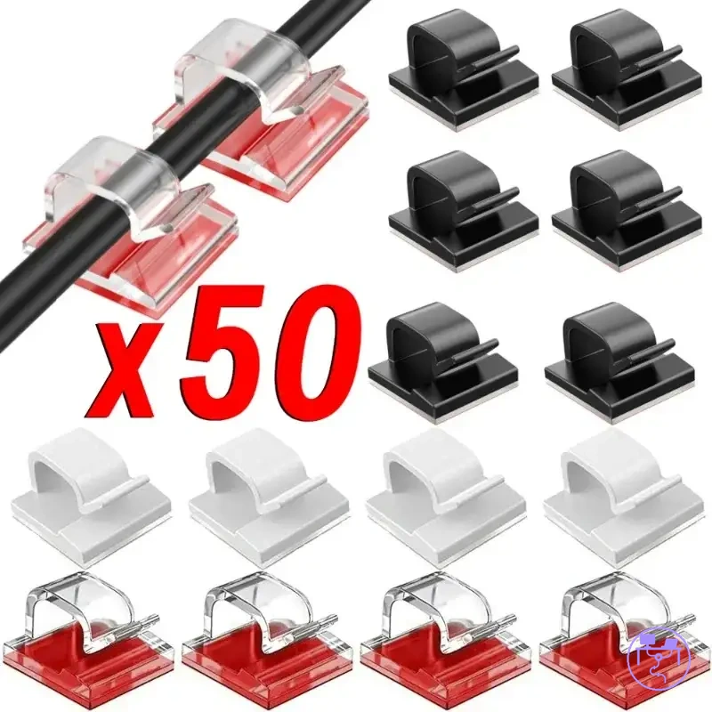
Clips, ties, and mounts for cable control points
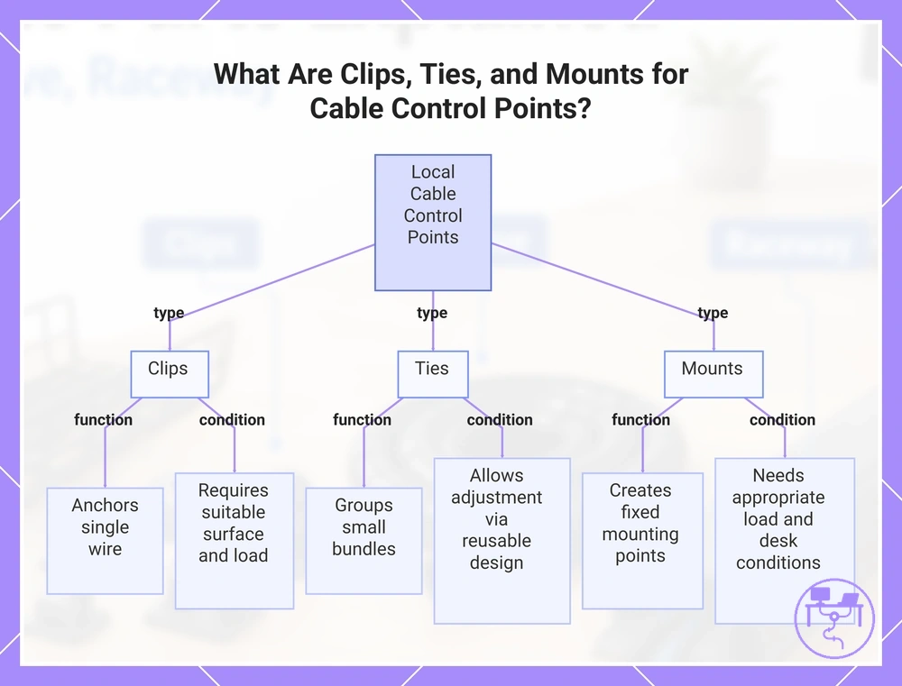
Clips, ties, and mounts are local cable control points that position individual wires or small bundles along a cable path. These parts help control cable direction, slack, and placement at specific locations rather than managing an entire cable run.
- Clips can anchor a single wire to a surface when precise cable positioning is needed.
- Ties can group a small bundle and may allow future adjustment when reusable designs are used.
- Mounts can create fixed mounting points that help maintain cable position under an appropriate load.
- Removable clips or straps may help redirect slack when cable paths change over time.
- Adhesive cable clips can provide local hold when the surface condition, material, and load are suitable.
Clips, ties, and mounts differ by attachment type, adjustability, and cable condition. Adhesive options depend on surface cleanliness and material, while fixed mounts may provide more stable cable positioning when load and desk conditions are appropriate. Reusable ties support adjustability, whereas fixed ties help maintain a defined bundle position. Cable weight, bundle size, and surface characteristics all influence control-point performance.
Adhesive performance, removal behavior, and residue risk may vary by desk material, load, surface condition, and removal method, so hold strength should be evaluated according to the specific application rather than assumed to be permanent.
This chart shows the three types of local cable control points and their specific functions and conditions.
Grommets and pass-through parts for desktop cable entry
Grommets and pass-through parts are desktop cable entry components that control how cables move between the work surface and the underside route. A grommet or pass-through guides cable direction through a desktop opening while providing edge protection and a more organized desktop cable entry point.
- Verify that the hole size suits the intended cable entry opening.
- Check that the cable count fits the available entry space.
- Confirm that edge protection is present where cables contact the opening.
- Ensure the cable direction aligns with the intended underside route.
- Review underside clearance for cable movement and access.
A grommet qualifies a desktop opening through hole size, edge protection, and cable count considerations. A pass-through helps cables pass through the desk surface and continue toward the underside route while maintaining cable direction. Reduced cable rubbing depends on opening condition, cable count, and the fit between the cable entry insert and the desktop opening. This section focuses on cable entry and edge control rather than desk modification or installation instructions.
Power strip holders and under-desk power support parts
Power strip holders and under-desk power support parts are components that support and position heavier power-related items rather than ordinary wire clips. A power strip holder helps hold a power strip or adapter in a defined location, which can improve access and organization when the holder matches the intended load and mounting condition.
- Load rating should suit the weight and size of the power strip or adapter.
- Mounting method should match the available desk surface and support condition.
- Ventilation space should remain appropriate for the supported power-related items.
- Access should allow reasonable reach to switches and plugs.
A power strip holder qualifies support through load rating, mounting style, ventilation, and access considerations. Under-desk power support parts can help separate a power strip or bulky adapter from surrounding cables while maintaining serviceability. Stability and reach depend on holder design, adapter bulk, mounting condition, and available space. Ventilation needs may vary with cable density and the condition of the supported items.
Under-desk power support parts organize and hold power-related items, but they do not replace proper electrical rating, routing, strain relief, or local electrical conditions. Any safety-related outcome depends on the power cord, equipment condition, installation quality, and surrounding environment rather than the holder alone.
Part attributes that change cable capacity, visibility, and access
Part attributes that change cable capacity, visibility, and access explain why similar cable management parts behave differently under the same desk conditions. Capacity, visibility, access, attachment, and adjustability are the main attributes used to compare how a part affects cable load, visual cleanliness, maintenance access, and future changes.
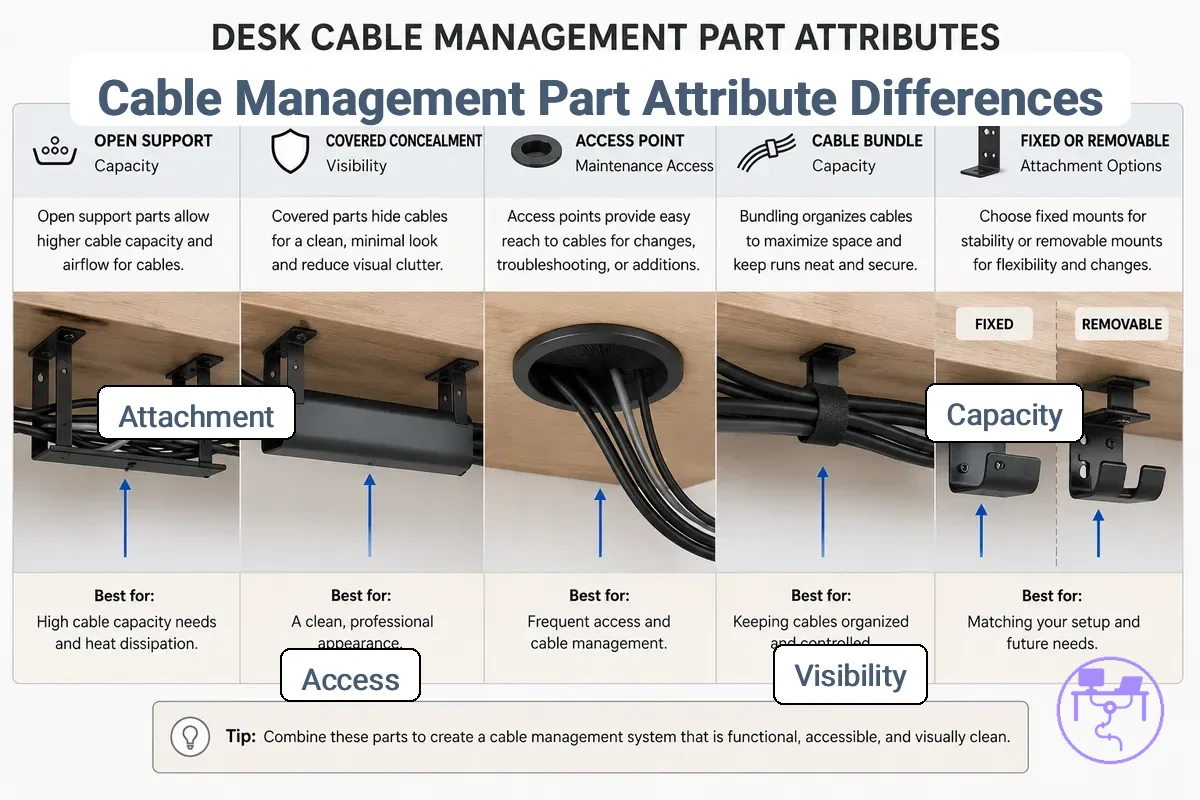
Part attributes that change cable capacity, visibility, and access can be compared through a simple entity-attribute-value structure. The table below connects a part, an attribute, a condition, and the resulting effect or decision. This approach highlights attribute behavior across part families rather than focusing on specific products.
| Entity/part | Attribute/criterion | Value/condition | Effect/risk/decision |
|---|---|---|---|
| Support part | Capacity | Higher cable load | May provide better support when cable load remains suitable for the part |
| Concealment part | Visibility | Greater cable concealment | Can improve visual cleanliness but may reduce access |
| Access-focused part | Access | Open cable route | May simplify maintenance access and future changes |
| Mounted part | Attachment | Fixed condition | Can improve position stability but reduce removability |
| Adjustable part | Adjustability | Removable condition | May support future changes with easier repositioning |
Capacity, visibility, access, attachment, and adjustability create the main trade-offs between part types. Greater cable concealment can improve visual cleanliness, but service access may become more limited because cables are less exposed. A fixed attachment may hold position more consistently, while a removable approach can make future changes easier. Outcomes depend on cable load, desk fit, maintenance access needs, and the condition of the cable route.
When a deeper comparison between individual component categories is needed, see tray raceway sleeve and clips compared.
Open support parts versus covered concealment parts
Open support parts versus covered concealment parts differ in exposure, access, and visual control. Open support parts such as a tray or J channel keep more of the cable route visible and accessible, while covered concealment parts such as a raceway or sleeve reduce exposure and place greater emphasis on visual control.
| Open support parts | Covered concealment parts |
|---|---|
| Higher visibility | Reduced visibility |
| Easier cable access | Access may be more limited |
| May suit a heavier bundle or changing cable route | May suit a visible cable problem where concealment is preferred |
| Often easier to adjust when changes occur frequently | Often more suitable when the cable route changes less often |
Open support parts expose more of the cable route, while covered concealment parts conceal or group cables to improve visual control. This difference creates a trade-off between access and concealment rather than a universally better option. An open tray or J channel may be preferable when a changing cable route requires easier access, while a raceway or sleeve may be preferable when reducing visible cables is a higher priority. For example, when cable adjustments happen frequently, visibility can matter more than concealment because maintenance access remains simpler.
Fixed attachment parts versus reusable cable control parts
Fixed attachment parts versus reusable cable control parts differ in permanence versus reusability. Fixed attachment parts such as an adhesive clip or screw mount prioritize maintaining cable position, while reusable cable control parts such as a reusable tie or removable strap prioritize adjustability and reconfiguration when cable layouts change.
- A suitable desk surface may support an adhesive clip, but residue can vary by desk material, load, and removal method.
- A screw mount may suit higher-load conditions when attachment permanence is a priority and surface alteration is acceptable.
- A reusable tie may be preferable when change frequency is high and cable bundles require periodic reconfiguration.
- A removable strap may support easier adjustment when future changes and cable access remain important.
- Heavier cable bundles can make load and long-term holding conditions more relevant to the attachment decision.
Desk surface, change frequency, residue, and reconfiguration are the main criteria that differentiate these attachment approaches. An adhesive clip depends on surface condition and may leave residue under certain removal conditions. A screw mount can increase attachment permanence, but suitability depends on surface characteristics and intended load. Reusable cable control parts emphasize adjustability and may simplify reconfiguration when cable layouts change regularly.
For renters or frequently changed setups, reusable ties and removable straps may provide greater flexibility because attachment points can be adjusted more easily. Fixed attachment parts may remain appropriate when long-term positioning is a higher priority, but the decision depends on desk surface, cable bundle condition, and expected future changes.
Desk fit factors that affect which parts can be used
Desk fit factors determine which parts can be used because compatibility depends on the mounting surface, underside clearance, cable load, and access conditions. Desk fit helps qualify whether a part size and attachment method are practical for a specific desk configuration.
Desk fit factors that affect which parts can be used can be evaluated by checking visible desk conditions before selecting a part. The image labels the desk conditions that influence fit, stability, and access outcomes for common cable management components.
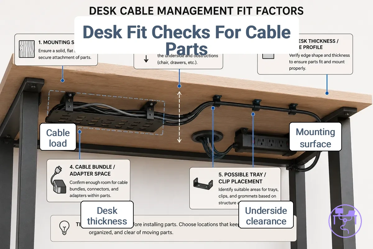
Desk compatibility depends on condition-based verification rather than assumptions. Use this checklist to verify whether the desk can accommodate the intended part and cable arrangement.
- Verify that the mounting surface provides enough mounting area for the intended attachment method.
- Check underside clearance to confirm that the part size can fit without limiting cable routing or access.
- Review desk thickness or edge profile when a clamp, screw, or adhesive condition affects installation.
- Compare cable load and adapter bulk with the available support space.
- Confirm that the mounting area allows reasonable access for maintenance and cable changes.
- Consider whether future removal or repositioning may affect the attachment choice.
Fit verification becomes more important when underside clearance is limited, cable load increases, adapter space is restricted, or access is constrained by the desk underside. These conditions can affect stability, routing flexibility, and maintenance access, making them useful decision signals to verify fit before choosing parts.
Desk fit determines whether mounting surface conditions, clearance check results, and cable load requirements support practical use of a part. When compatibility remains uncertain, it is useful to choose parts for your setup using fit-based criteria before making a decision.
The products below are useful examples for comparing available options. Before buying, check that the compatibility criteria, key features, and product details match your needs.
Mounting surface, desk thickness, and underside clearance
Mounting surface, desk thickness, and underside clearance limit attachment choices because these conditions determine whether a clamp, adhesive, screw, or no-drill attachment method may be suitable. Mounting success depends on desk material, available mounting area, and the clearance space beneath the desk.
A mounting surface may qualify adhesive suitability based on material and surface condition. Desk thickness and edge profile can limit or allow clamp suitability depending on available grip area. Underside clearance may block placement when an obstruction reduces access or available space for a tray, clip, or similar part. Screw-based attachment methods may be suitable in some conditions, but permanent mounting decisions should be verified before altering the desk.
- Verify that the mounting surface condition suits the intended attachment method.
- Check whether desk thickness and edge profile may limit clamp suitability.
- Confirm that underside clearance provides enough space for the selected part and cable access.
- Review nearby obstruction points that may reduce clearance space or block placement.
- Compare clamp, adhesive, screw, and no-drill suitability against the available mounting area.
- Consider whether future access needs may affect attachment suitability.
Cable bundle size, adapter weight, and power strip space
Cable bundle size, adapter weight, and power strip space affect compatibility because cable load includes wire count, bundle diameter, adapter bulk, and access needs. These conditions help qualify tray capacity, holder capacity, sleeve suitability, and clip suitability without assuming capacity beyond product-rated information.
| Load condition | What to check | Part affected | Possible outcome |
|---|---|---|---|
| Light | Wire count and cable volume | Sleeve or clip | Less crowding and easier access |
| Moderate | Bundle diameter and adapter bulk | Tray or sleeve | Access may become more limited |
| Heavier | Adapter weight and power strip space | Tray or holder | Crowding, strain, or sag may increase |
Cable bundle size can affect tray capacity because larger bundle diameter and cable weight may increase sag when support conditions are limited. Adapter weight can affect holder capacity, stability, and access when adapter bulk occupies more space than expected. Power strip space influences clearance, ventilation, and serviceability because crowded layouts may reduce access to cables and connected devices. A light peripheral-cable setup may place fewer demands on support parts, while an adapter-heavy or power-strip-heavy setup may require closer attention to cable load, crowding, and strain outcomes that depend on product-rated information and installation conditions.
How parts work together across one cable route
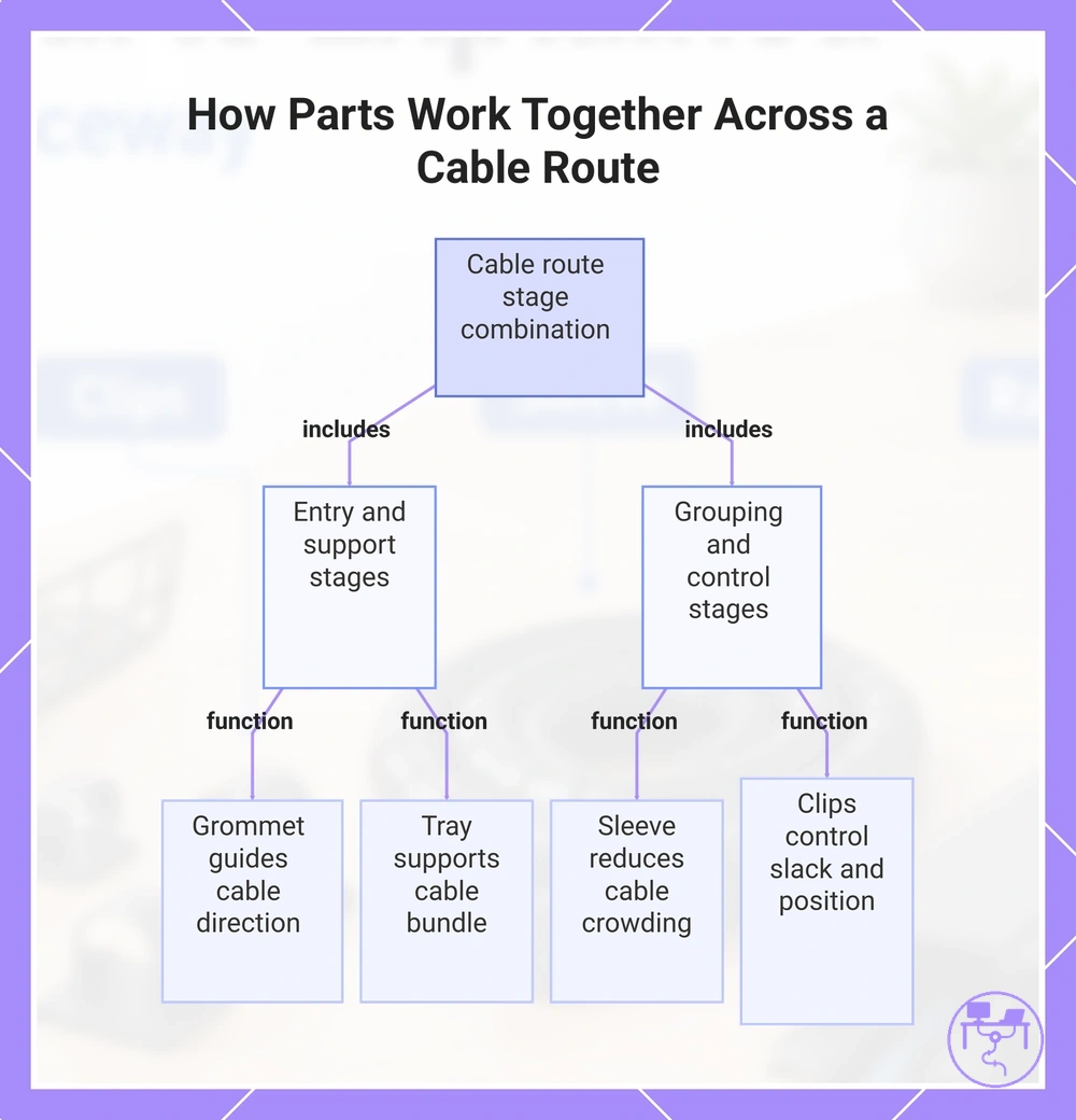
How parts work together across one cable route is defined by the different functions that manage each stage of the cable route. A cable route usually needs entry, support, grouping, and control points because different parts handle different attribute needs and contribute to the overall outcome.
The cable route combines connected stages rather than relying on a single part. Desktop entry helps connect a visible cable path to the underside route, under-desk support helps carry a cable bundle, bundle grouping helps manage cable volume along the cable run, and endpoint control helps manage slack and cable position. Each stage connects to a specific attribute need that influences part choice and access conditions.
- Entry point: A desktop entry component such as a grommet helps guide direction from the desk surface to the underside route.
- Under-desk support: A tray or similar support part helps support a cable bundle and maintain access along the cable route.
- Bundle grouping: A sleeve or grouping part helps group cables and reduce crowding along the routing path.
- Endpoint control: Clips, ties, or similar control points help control slack and cable position near the end of the wire route.
If a cable route includes peripheral cables, an adapter, and a power connection, the route may connect a desktop entry point to under-desk support, continue through a grouping stage, and finish at endpoint control locations. The outcome can vary by desk layout, cable count, and the attribute need associated with each stage.
This chart shows the four main stages of a cable route and the function of each stage.
Part-specific limits before installation or routing
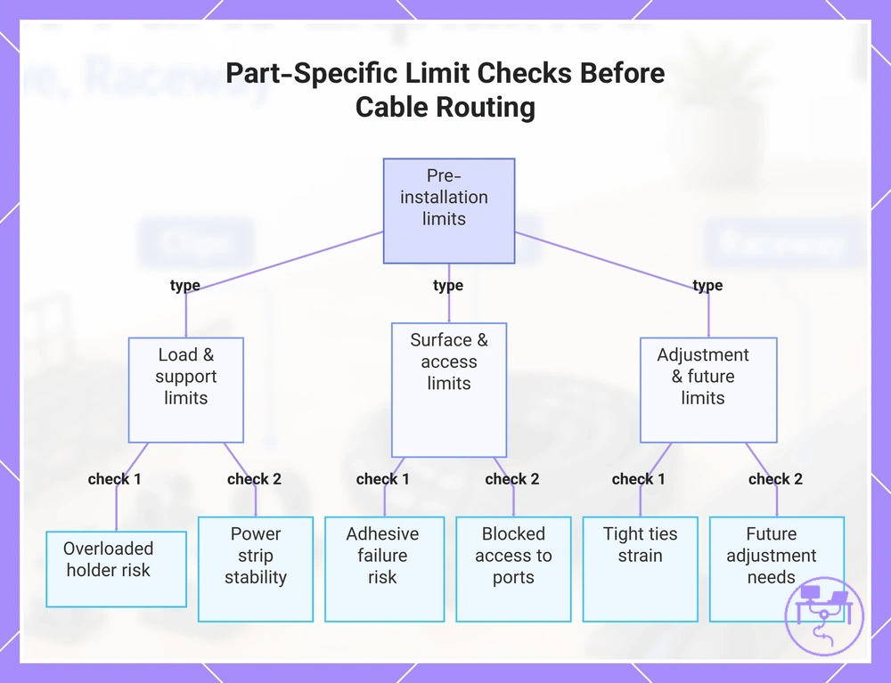
Part-specific limits should be checked before installation or routing because load, surface, access, power, and adjustment conditions can affect whether a part remains suitable for the intended cable route. These pre-installation limits help qualify decisions before action is taken.
Load limits can affect support parts when cable weight, adapter bulk, or power-related items exceed practical conditions for the selected part. Surface limits can affect attachment reliability, while access limits may reduce maintenance or adjustment flexibility after routing. Power support conditions can influence stability, and adjustment limits can become relevant when future cable changes are expected.
The checklist below highlights common part-specific limits that may influence routing decisions. These checks focus on conditions and practical limits rather than installation procedures.
- Check whether cable load may contribute to an overloaded holder under the intended condition.
- Check whether surface condition and cleanliness may increase the risk of adhesive failure.
- Check whether part placement could create blocked access to cables, ports, or adjustment areas.
- Check whether power strip or adapter size may affect stability, clearance, or support conditions.
- Check whether tight ties may increase strain or reduce adjustment flexibility.
- Check whether cable crowding may limit access or cable organization along the route.
- Check whether future adjustment needs may influence part choice and routing decisions.
This section flags limits before action and does not teach the full installation process. If execution steps are needed, see how to install desk cable management parts.
This chart shows the main categories of pre-installation limits and the specific checks to perform before routing cables.