Desk Cable Management System for Multiple Monitors
Desk cable management system for multiple monitors depends on matching cable volume, routing needs, power placement, and desk fit to a specific workstation configuration. Extra displays create additional monitor cables, power cords, and peripheral cable paths that often require more planning than a single-screen setup. For this page, compatibility is the primary decision frame.
Multiple monitors increase cable load and can make cable routing more complex around an under-desk tray, power strip, and desk access points. A setup with more display cables, power adapters, and connected devices may require different routing paths than a simpler arrangement. Power placement, cable length, and access requirements can also affect how easily cables are organized and maintained. Because these conditions vary, selection should be based on the setup rather than a single cable organizer approach.
A dual monitor workstation may have different routing needs than a larger multi-monitor setup with docking devices and additional peripherals. Workstations that use monitor arms can introduce cable exit points, movement clearance, and slack requirements that do not exist with fixed monitor stands. In other cases, a docked workstation may combine display cables, power cords, and peripheral connections into a denser cable bundle. These differences make system requirements dependent on the workstation layout rather than monitor count alone.
The right desk cable management system depends on desk size, monitor count, cable length, power needs, and physical access conditions. Readers who want a broader overview can also explore the desk cable management system hub before evaluating a multi-monitor setup. Compatibility may change when cable load, monitor arms, rear desk edge routing, or power strip placement create different fit requirements.
This page focuses on the practical conditions a multi-monitor system must handle before trays, sleeves, clips, ties, or holders are considered. The first step is understanding how grouped monitor, power, and peripheral cables affect cable load, routing access, and desk fit beyond general desk tidiness.
What a multiple-monitor cable management system must handle
A multiple-monitor cable management system must handle grouped cable volume, routing access, power placement, and desk fit across a workstation with more than one display. As monitors, peripherals, and connected devices increase, the cable bundle often becomes larger and may require more routing paths and access points. More screens naturally multiply cable paths that need to remain organized and accessible.
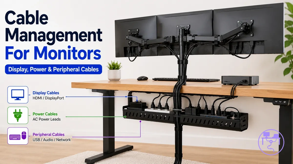
What a multiple-monitor cable management system must handle includes more than monitor cables alone. Typical grouped cable demands include display cables, power cords, peripheral cables, and docking cables that may connect through USB hubs, adapters, or other workstation components. Each cable group can have different thickness, flexibility, and routing requirements. Together, these cable groups influence cable access, desk space, and underside clearance.
Neat cable appearance can support organization, but a tidy-looking setup does not automatically mean cable routing, access, and clearance needs are being met. A multi-monitor setup may still require room for cable movement, maintenance access, and future changes even when cables appear controlled. Multi-monitor compatibility extends beyond general desk cable tidiness because it focuses on managing workstation cable demands under practical operating conditions.
What a multiple-monitor cable management system must handle:
- Display cables: Additional displays can increase cable count and routing pressure as monitor connections expand.
- Power cords: Monitor and device power connections may require coordinated placement around a power source and cable route.
- Peripheral cables: Keyboards, webcams, audio devices, and other accessories can add separate cable runs that affect cable access.
- Docking cables: USB hubs, docking stations, and adapters may concentrate workstation cables into a single area that requires clearance and access.
- Desk space and fit: Available desk space, underside clearance, and cable bundle size can influence routing options and organization.
- Cable access: Access points should remain reachable because cable changes and workstation adjustments may occur over time.
Cable load and desk fit for dual and multi-monitor setups
Cable load and desk fit depend on how many cables a dual monitor or multi-monitor setup must hold and how much usable desk space is available under and behind the workstation. A cable bundle that fits one desk may not fit another because desk construction, monitor count, and hardware layout can change the available mounting space.
Cable count, cable thickness, adapter bulk, and tray capacity should be judged together before choosing storage. Thicker monitor cables and larger power adapters can occupy more tray space than slim peripheral leads. If the cable load is dense, the storage choice may need more open access, stronger mounting support, or a different cable path rather than a single hidden route.
A compact desk may have limited underside mounting area and tighter rear-edge access, so physical clearance can become the main constraint. A deep desk may provide more routing space, but cable reach and access can still affect where the under-desk tray or holder sits. A workstation with monitor arms may also need slack for monitor arm movement, cable exit points, and rear clearance. In each case, physical clearance decides whether the system is practical before parts are selected.
Use the checklist below to separate cable load criteria from desk fit criteria before selecting trays, sleeves, clips, or ties. Cable load and desk fit for dual and multi-monitor setups should be verified where cable volume and physical clearance meet.
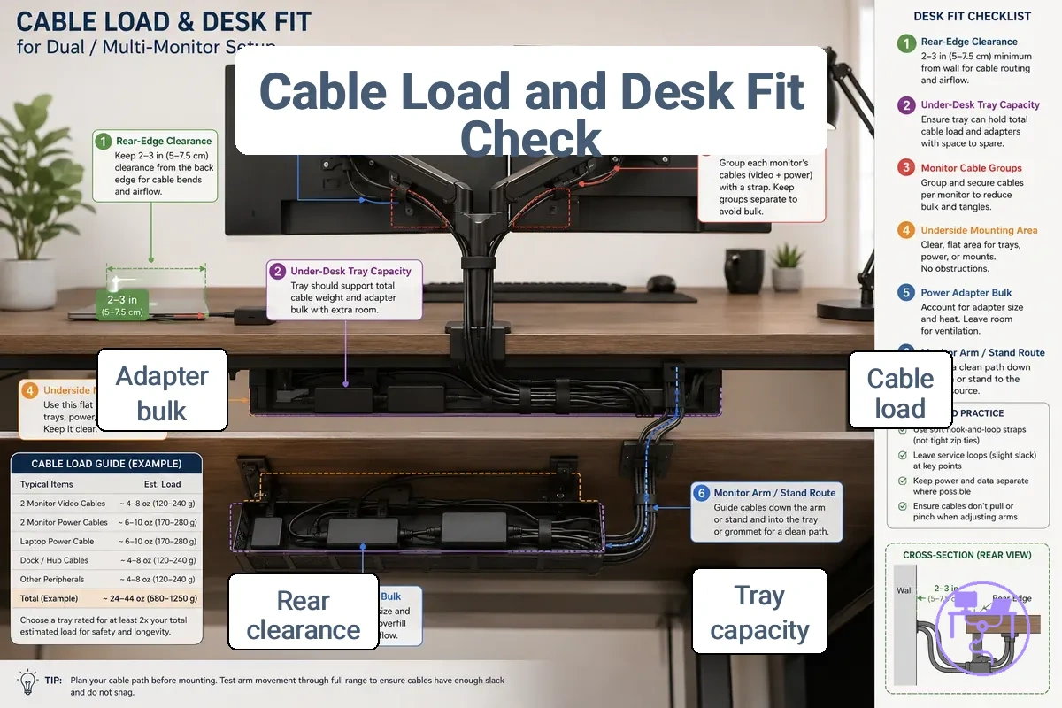
- Cable load: Check whether the cable bundle size can sit inside the planned route without forcing sharp bends or blocking access.
- Cable thickness: Review thicker display cables, power cords, and adapter leads because bulkier cables can reduce usable tray capacity.
- Adapter bulk: Confirm that power adapters have enough space around the power strip, holder, or tray area without crowding other connections.
- Underside mounting area: Verify that the desk underside has a usable mounting surface before relying on an under-desk tray or holder.
- Rear-edge access: Check whether monitor cables can drop from the rear edge into the desk system without being pinched or stretched.
- Monitor arm movement: Leave condition-based slack when monitor arms, adjustable screens, or moving cable paths change the exit point.
For a fuller desk compatibility check, compare these conditions with the fit and mounting factors before treating the setup as ready for a cable management system.
Display, power, peripheral, and docking cables
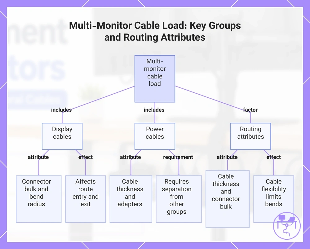
Display cables, power cables, peripheral cables, docking cables, charging cables, and hub cables are the cable groups that usually increase load in a multi-monitor workstation. Each cable group adds different routing demands, which helps inform the parent cable-load check.
Cable thickness, connector bulk, and cable flexibility can affect how easily a cable route changes direction or passes through a workspace. Thicker cables and larger connectors may require more routing space, while less flexible workstation cables can limit bend options. For example, adding one extra monitor may introduce both an additional display cable and a power cable, creating more than one cable path.
- Display cables: Connector bulk and bend radius can affect how monitor cables enter and leave a route.
- Power cables: Cable thickness and adapters may require greater separation from other cable groups.
- Peripheral cables: Cable flexibility can affect how device cables route around accessories.
- Docking cables: Connector bulk and docking changes may affect access when devices are added or removed.
- Charging cables: Length and connector type can influence cable paths between powered devices and charging sources.
- Hub cables: Connections between hubs and devices may change routing when workstation layouts evolve.
This chart shows the main cable groups and routing attributes that increase cable load in a multi-monitor workstation.
Desk underside space, tray capacity, and rear-edge clearance
Desk underside space and rear-edge clearance determine whether grouped monitor cable storage remains practical and accessible. A storage solution depends on available underside space, tray capacity, and cable routing conditions, especially when cable bundles and desk layouts vary.
Tray width, tray depth, and the available mounting surface influence how easily cables can be organized and accessed. A larger cable bundle or added adapter bulk may use more tray capacity, while an interrupted mounting surface can limit placement options. When multiple storage positions seem possible, open access is often the deciding factor.
Use this checklist to verify Desk underside space, tray capacity, and rear-edge clearance before organizing grouped monitor cables:
- Underside space: If under-desk space is limited, cable storage may require a smaller routing footprint.
- Tray width: If tray width is narrow relative to the cable bundle, cable organization can become more restrictive.
- Tray depth: If tray depth extends too far downward, legroom may be reduced.
- Mounting surface: If the mounting surface is uneven or interrupted, storage placement may become less practical.
- Rear-edge clearance: If rear-edge clearance or a rear desk lip restricts access, cable drop points for monitor cables can become tighter and harder to route.
- Port access: If storage capacity occupies connection areas, port access may become less convenient.
Large tray capacity can help manage dense cable bundles, but it should not block legroom or port access during normal workstation use.
Monitor arm clearance and cable exit points
Monitor arm clearance and cable exit points depend on how the cable path changes as a monitor arm moves. In a typical monitor arm route, cables leave the display near the VESA position, pass through arm channels, and exit near the clamp area before continuing toward a desk-edge route. This changing path usually requires enough monitor arm clearance around the cable route and nearby desk surfaces.
Cable exit points, slack, and bend radius influence how cables move with a moving arm. If slack is limited, cables may become tighter as the arm changes position, while a restricted bend radius near the VESA position or desk-edge exits can reduce routing flexibility. Movement clearance depends on arm design, cable length, and the selected cable path.
A fixed stand often keeps cable exit points in a more consistent location, while adjustable monitor arms can shift cable paths as the display moves. Because arm channels, clamp area layouts, and rear desk exit locations vary by design, cable planning should account for movement clearance rather than relying on a single routing pattern.
Choosing trays, sleeves, clips, and ties for monitor cables
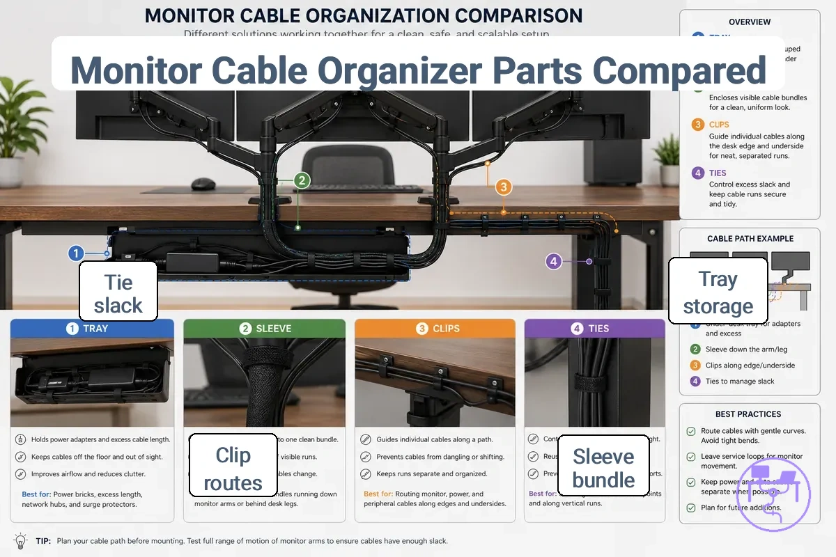
Part selection depends on matching each cable-control job to the right organizer rather than relying on a single solution. Most multi-monitor setups need a mix of trays, sleeves, clips, and ties because monitor cables often require different forms of control. The selection decision should follow the part-to-job relationship.
Choosing trays, sleeves, clips, and ties for monitor cables is easier when the image below compares what each part controls and where it is typically used.
| Part | Controls | Best use case | Limitation to check |
|---|---|---|---|
| Tray | Grouped cables and cable load | Under-desk tray for multiple monitor cables | Capacity and access |
| Sleeve | Visible bundle | Keeping related monitor cables together | Access to individual cables |
| Clips | Separate cable runs | Guiding cables along a route | Route changes may require repositioning |
| Ties | Slack and adjustment | Managing excess cable length | Bundle tightness during future changes |
| Holder or channel | Cable direction | Maintaining a defined cable path | Available mounting location |
Trays, sleeves, clips, and ties are functional categories rather than interchangeable cable organizer parts. An under-desk tray manages grouped cables and cable load, while a sleeve organizes a visible bundle without separating related cables. Clips direct separate cable runs along a chosen route, and reusable ties control slack where adjustment may be needed. Each part connects a specific attribute to a specific use case.
When monitor cables include grouped sections, visible sections, and separate cable runs, combining parts is often more practical than selecting only one organizer type. A tray can manage the main cable load, a sleeve can organize a visible bundle, clips can guide routes, and ties can maintain adjustable slack. The decision signal is whether the setup contains more than one cable-control job. If multiple control methods are needed, it may help to choose a system for cable load before final part selection. Part selection works best when trays, sleeves, clips, ties, holders, and channels are matched to cable load, visibility, access, and routing requirements.
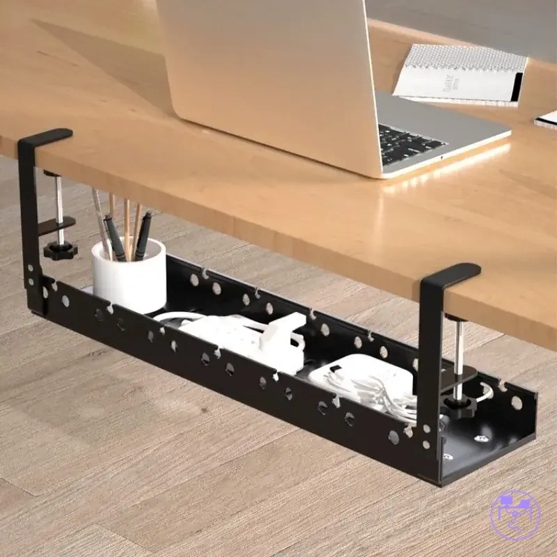
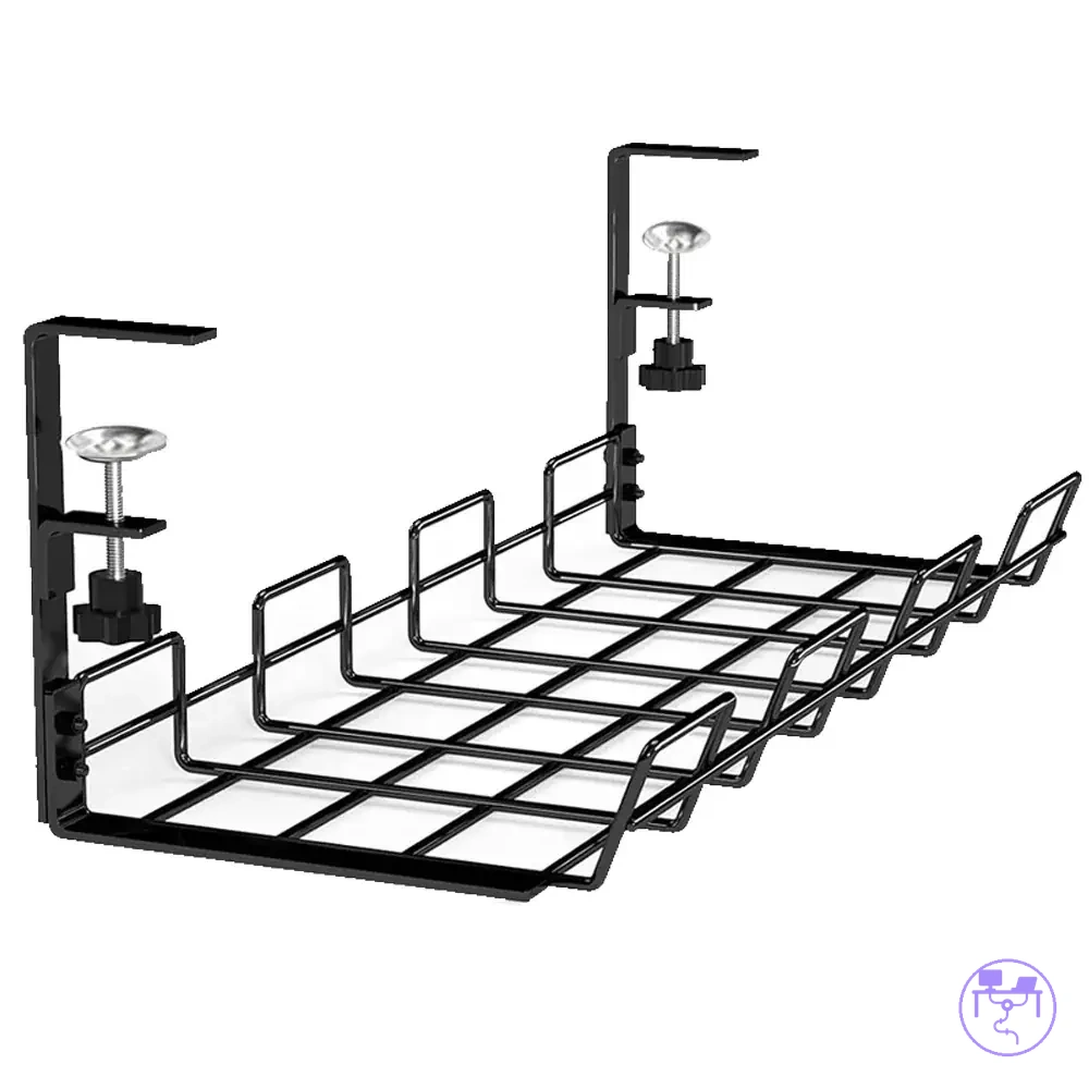
Large under-desk trays for grouped monitor cables
A large under-desk tray is useful when grouped monitor cables, power cables, and peripheral cables need shared storage beneath the desk. Larger tray size can support a higher cable load, but suitability depends on tray attributes, available space, and access requirements. Capacity is most relevant when multiple cable groups need organized and accessible storage.
| Tray attribute | Helpful condition | Risk to check |
|---|---|---|
| Tray length | More room for grouped cable storage | May extend beyond useful routing areas |
| Tray depth | Additional space for cable bundles | Can reduce clearance on a shallow desk |
| Openness | Easier cable separation and serviceability | Less concealment of visible cables |
| Weight support | Supports larger cable loads | Depends on mounting conditions |
| Access | Simplifies cable changes and maintenance | Limited access can slow adjustments |
Tray length, tray depth, openness, weight support, and access each influence how a large under-desk tray performs for grouped cable storage. Greater openness can improve cable separation between power and display cables and make serviceability easier when changes are needed. Weight support matters because grouped monitor cables, adapters, and peripheral connections can increase cable load over time, while access affects how easily cables can be reached after setup changes. If a desk is shallow, increased tray depth may create clearance concerns near legroom or other under-desk areas, making tray depth an important condition to verify.
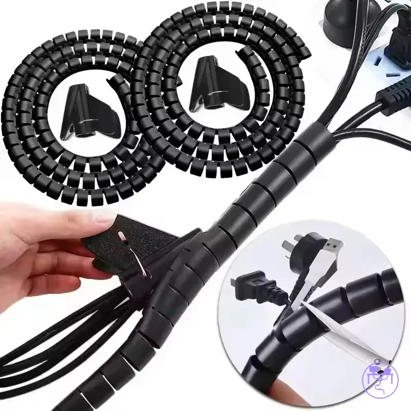
Sleeves and wraps for visible monitor cable bundles
Sleeves and wraps help organize visible monitor cable bundles that run between monitors, monitor arms, and the desk edge. They keep related cables together along a visible route, while suitability depends on sleeve diameter, cable count, visible path length, and access frequency. Sleeve fit conditions determine how effectively a visible bundle can be managed.
- Sleeve diameter: Bundle fit depends on matching sleeve diameter to cable count and overall bundle size.
- Cable count: A larger cable count may require additional internal space to maintain access to the visible bundle.
- Visible path length: Longer routes between a monitor arm and desk edge may benefit from more continuous bundle control.
- Split design: A split design can improve serviceability when cables are added, removed, or repositioned.
- Access frequency: Frequent cable changes may favor sleeves and wraps that allow easier access to individual cables.
Flexibility affects how sleeves and wraps follow bends around a monitor arm or along a desk-edge route, while a split design can reduce disruption when cable layouts change. Higher access frequency may make a cable sleeve, cable wrap, or cable cover more practical when individual cables need adjustment. Unlike under-desk storage, which focuses on storing cables beneath the workspace, sleeves and wraps focus on controlling a visible bundle along the cable path.
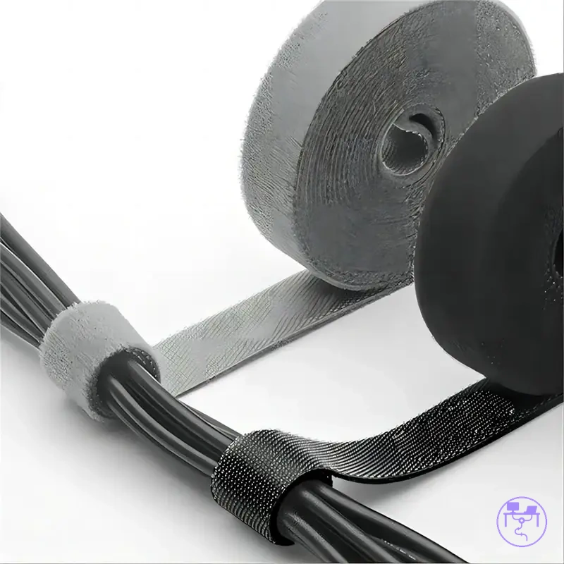
Clips and reusable ties for separate cable runs
Clips and reusable ties help keep separate cable runs organized while allowing cable layouts to change over time. They guide cable routes, manage slack, and maintain separation between cables without permanently locking the setup. Adjustment needs should determine how clips and reusable ties are applied.
Use the checklist below to match clip and tie conditions to separate cable runs and future access requirements:
- Adhesive clips: May help guide a cable route when the desk material and mounting surface are suitable, but hold can vary by surface condition.
- Screw clips: Can support a more fixed routing path when a mounting point is available and future adjustments are less frequent.
- Reusable ties: Useful for managing slack when cable lengths change or equipment is repositioned.
- Hook-and-loop straps: Help maintain cable spacing while allowing easier adjustment and future access to individual cables.
- Cable spacing: Separate cable runs can remain easier to trace and adjust when routing paths avoid unnecessary overlap.
Clip type, tie type, cable spacing, and future access should be considered together because cable layouts may change after installation. Adhesive clips and screw clips influence how cables follow a route, while reusable ties, hook-and-loop straps, and other cable straps affect how easily slack can be adjusted. For example, display cables and power cords can follow separate paths to reduce clutter and make future access easier when changes are needed.
Power strip placement for multiple monitor setups
Power strip placement for multiple monitors depends on balancing cord reach, access, and rated capacity. Placement should allow power cords and adapters to connect without creating unnecessary strain or blocking nearby outlets. Safety considerations depend on equipment count, power demand, and the chosen location.
Power demand and physical placement interact through outlet count, adapter spacing, cord reach, and holder location. A suitable outlet count may still be difficult to use if large adapters reduce available space. Cord reach should allow monitors and accessories to connect without forcing connections, while a practical holder location can help keep power access visible. Access remains important because devices, adapters, and power cords may need future adjustment.
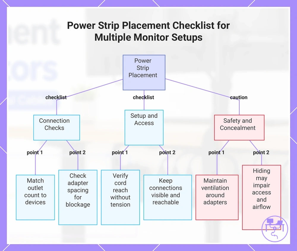
Use this safety checklist to verify power strip placement conditions before finalizing a multiple-monitor setup:
- Outlet count: Confirm that available outlets match connected devices without relying on crowded power arrangements.
- Adapter spacing: Check whether bulky adapters may block adjacent outlets or reduce access.
- Cord reach: Verify that power cords can reach the power strip without excessive tension.
- Surge protection: If surge protection is required, confirm that the surge protector suits the intended placement and usage conditions.
- Holder location: Choose a power strip holder location that keeps connections reachable when adjustments are needed.
- Ventilation: Avoid placement conditions that may restrict airflow around adapters or under-desk power components.
- Access: Keep plugs and connections visible enough for inspection and future changes.
Hiding a power strip is not always safer or more practical than keeping it visible. A concealed power bar may reduce visible clutter, but ventilation, adapter spacing, and access can become harder to evaluate depending on placement. Detailed power-cord safety considerations belong to a dedicated electrical-safety context when more specific guidance is needed.
This checklist shows key conditions to verify when placing a power strip in a multiple-monitor setup, including connection, access, and safety checks.
Outlet count, adapter spacing, and surge protection
Outlet count, adapter spacing, and surge protection are power strip attributes that can affect multiple monitor setups. Plug size, transformer blocks, cord length, switch access, and rated capacity influence how devices connect and remain accessible, making these attributes part of the overall placement decision.
Bulky adapters can reduce usable outlet space when transformer blocks extend into adjacent positions. A power strip switch can also become less convenient to reach if placement does not account for routine access. In one edge case, a large adapter may block a neighboring outlet, so outlet availability and rated capacity should be reviewed with caution rather than assumed.
Use the checklist below to connect outlet count, adapter spacing, and surge protection attributes to practical planning effects:
- Outlet count: A higher socket count may support additional connections when device requirements increase.
- Adapter spacing: More adapter clearance can improve access when bulky adapters or transformer blocks are present.
- Surge protection: Surge protection should be considered alongside rated capacity and intended usage conditions.
- Cord length: Appropriate cord length can improve placement flexibility and power-cord reach.
- Switch access: Easy access to the power strip switch can simplify routine power control after placement.
Power strip holders inside or beside the cable tray
Power strip holder placement depends on switch access, heat clearance, cable entry direction, and available weight support. A power strip holder may sit inside the cable tray, beside the cable tray, or in a separate location depending on tray openness and holder size. The placement decision depends on access requirements, clearance conditions, and cable routing direction.
Inside the cable tray placement can help keep cables and the holder in a shared area when tray openness, heat clearance, and weight support are suitable. Beside the cable tray placement may improve switch access and make cable entry direction easier to manage when routine adjustments are expected. A separate under-desk holder or power strip mount can help when tray space is limited, but the trade-off often involves clean appearance versus maintenance access rather than a universally preferred position.
Use this comparison to evaluate holder placement options:
| Placement choice | When it helps |
|---|---|
| Inside the cable tray | Useful when holder size, tray openness, and cable entry direction fit the available tray space. |
| Beside the cable tray | May improve switch access and simplify access when future cable changes are expected. |
| Separate placement | Can help when tray capacity, weight support, or clearance conditions make tray-based placement less practical. |
Routing monitor cables from screens to the desk system
Routing monitor cables starts by moving cables from screen exits toward a controlled entry point in the desk system. The cable path usually progresses from the screens to a monitor arm or rear edge, then toward the underside and an under-desk tray. The route should leave enough slack and maintain access points where future adjustments may be needed.
In a monitor arm setup, display cables and power lines often follow the arm before reaching the rear edge of the desk. From there, the cable route can transition toward the desk system through a defined route entry rather than crossing open workspace areas. This creates a more predictable underside transition into an under-desk tray.
When bend radius is too tight or cables enter the desk system without grouping, future adjustments may become more difficult. Grouping related cables can help organize the cable path, while separation between display cables and power lines may improve access and reduce routing congestion where cable density increases. Appropriate slack and gradual bends can support serviceability when monitors or connected devices are repositioned.
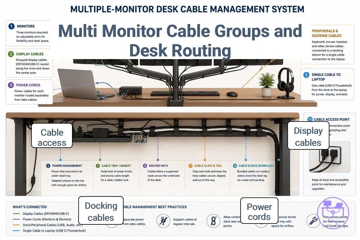
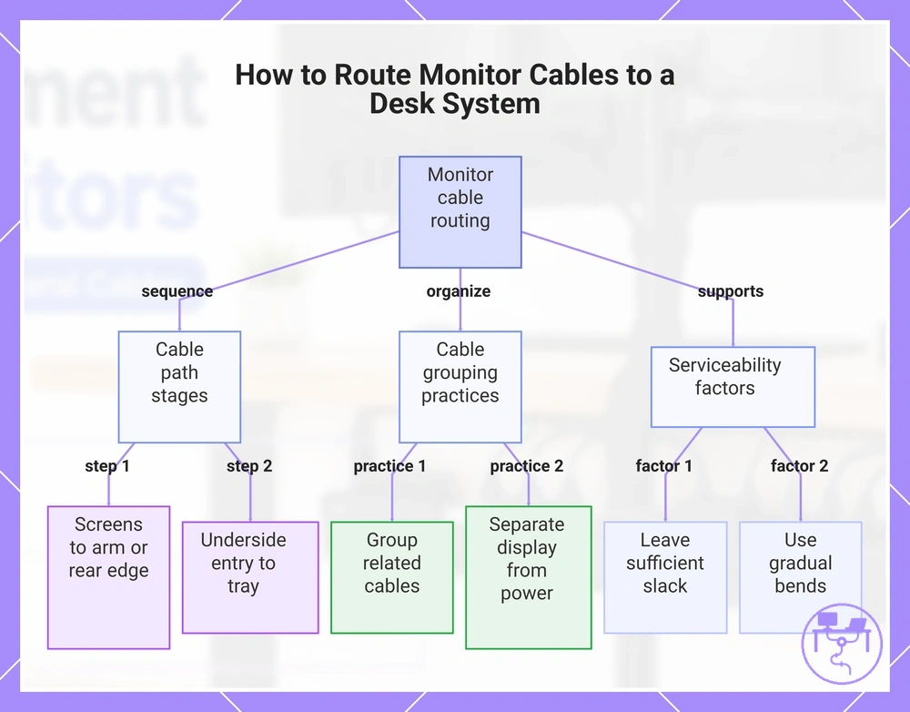
The typical route sequence is screens, monitor arm or rear edge, underside entry, and under-desk tray. For broader routing decisions after the screen-to-desk transition, it may help to route monitor cables under a desk while keeping monitor-specific access points visible and reachable.
- Start the cable path at the screen exits; if the screens move or tilt, leave enough slack to preserve access.
- Guide cables through a monitor arm or along the rear edge when available; if direction changes occur, maintain a suitable bend radius for easier routing.
- Group related monitor cables before the route entry point; if cable count increases, keep access points identifiable for future changes.
- Separate display cables from power lines where practical; if cable runs become crowded, separation may improve access and organization.
- Transition cables into the under-desk tray through a defined entry path; if the tray contains multiple cable groups, preserve serviceability by keeping the route accessible.
This chart shows the main stages of monitor cable routing from screens to the under-desk tray, along with key cable management practices and serviceability factors.
Routing through monitor arms and behind the desk
When monitor arms are used, the visible cable path usually follows an arm channel before moving behind the desk through rear edge drops. When cables leave the monitor arm or rear edge, cable exit direction, available clearance, and access points can shape the route and create local constraints.
When hinge movement changes the position of monitor arms, limited slack can make cable adjustment more difficult. Leaving appropriate slack around moving joints and using arm clips to guide the cable path may help maintain access as the route changes. Open rear edges often provide easier access to rear edge drops, while a wall-adjacent desk may reduce clearance and require more caution when accessing cables behind the desk.
- Guide cables through arm clips when available; if the monitor arm moves frequently, leave enough slack to support hinge movement and future adjustment.
- Direct the cable exit direction toward the rear route; if cables leave the arm at a sharp angle, keep the cable path accessible for repositioning.
- Use rear edge drops to move cables behind the desk; if rear clearance is limited, verify access before relying on the route.
- Check slack around moving joints; if cable length is tight relative to arm movement, routing flexibility and access may be reduced.
Routing under the desk without loose hanging cables
Under-desk routing starts with keeping monitor cables in a controlled run after they leave the monitor area. Loose hanging cables are less likely when the under-desk cable path follows a defined cable direction and reaches a controlled entry point through tray entry points.
When clips are spaced too far apart or tray entry points do not align with the cable direction, dangling cables can become harder to control. Tie spacing should reflect cable weight, desk material, and access needs rather than creating a permanent tie-down. For example, grouped display cables can enter a tray together while keeping power access or port access reachable for future changes.
- Clips: Use cable routing clips to guide the under-desk cable path; if cable weight varies, clip spacing may need adjustment to maintain control.
- Tray entry points: Route cables through defined tray entry points; if entry locations are inconsistent, cable direction may become harder to maintain.
- Cable direction: Keep cable direction consistent after cables leave the monitor area; if routes cross unnecessarily, access may become less convenient.
- Tie spacing: Leave tie spacing that supports grouping without limiting future cable changes; if ties are too close together, serviceability may be reduced.
- Underside clearance: Check underside clearance along the route; if cables pass through tight areas, access to power or ports may become more difficult.
Managing excess cable length without blocking access
Managing excess cable length starts with storing cable slack in a way that preserves access and avoids unnecessary strain. Excess cable length is easier to control when loops remain accessible, port access stays clear, and the stored length supports a serviceable setup.
When loops become difficult to reach or tie tension becomes excessive, future cable adjustments may require more effort. Bend radius and adapter weight can influence how spare length is stored, especially near connection points where access is needed. For users who make frequent future device changes, such as replacing monitors or docks, accessible loops can help maintain a serviceable setup without limiting adjustments.
Use the following do-and-avoid checks when handling excess cable length:
- Do: Store excess cable length in accessible loops when future adjustments may be needed.
- Do: Leave enough slack near connections to support port access and future device changes.
- Do: Consider bend radius when arranging loops so cable routing remains easier to adjust.
- Do: Account for adapter weight when storing spare length near adapters or connection points.
- Avoid: Increasing tie tension to the point that cable access or adjustment becomes difficult.
- Avoid: Positioning excess cable length where it may reduce port access or block routine changes.
- Avoid: Creating loops that concentrate strain in one area when the cable route changes.
- Avoid: Using a permanent bind when future device changes or cable replacement may be expected.
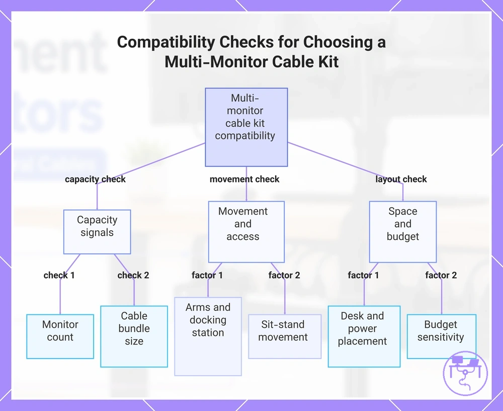
Compatibility checks before choosing a multi-monitor cable kit
Compatibility checks should happen before choosing a multi-monitor cable kit because kit suitability depends on workstation conditions, not a single product claim. Monitor layout, cable volume, desk space, and movement needs all affect whether a cable management kit will be practical. The better selection method is condition-based selection.
- Monitor count: Check how many screens add cables; choose more capacity only when the added cable load requires it.
- Cable bundle size: Check bundle thickness and adapter bulk; consider a larger kit if grouped cables exceed simple tie control.
- Desk underside space: Check usable mounting area; choose parts that fit without blocking legroom or access.
- Power strip location: Check reach and visibility; adjust kit choice if power access would be crowded or hidden.
- Monitor arms: Check movement and cable exits; add extra ties only where slack needs controlled adjustment.
- Docking station: Check short device runs and port access; use separate sleeves if visible cable groups need flexible access.
- Sit-stand movement: Check vertical travel and slack; choose parts that allow movement without forcing cable tension.
- Budget sensitivity: Check which parts solve actual cable-control jobs; avoid paying for unused kit pieces when targeted parts are enough.
Monitor count and cable bundle size are the first capacity signals to check. More screens can add display cables, power lines, adapters, and peripheral connections, which may increase the total cable bundle size. If the bundle is dense, a larger kit, extra ties, or separate sleeves may be needed to keep routing manageable.
In a workstation with monitor arms, a docking station, or sit-stand movement, the kit must allow movement without blocking access. Monitor arms may require slack near moving points, while a docking station can add short cable runs that need separate control. Sit-stand movement can also change the required cable path between the desktop and underside storage. These conditions make slack and access requirements part of the compatibility check.
Power strip location and desk underside space should be checked before selecting organizer parts. A kit may include trays, clips, or ties, but those parts still need usable mounting space and reachable power access. If the underside space is limited or the power strip location blocks access, kit fit may depend on a smaller layout or separate cable control parts.
Budget sensitivity should be evaluated against what the setup actually needs rather than the number of items in a kit. If a larger kit adds unused parts, separate sleeves or extra ties may be more practical; if the setup is expanding, compare the cost factors for larger setups before choosing. Upgrade signals include increasing monitor count, larger cable bundle size, added docking station use, or new sit-stand movement.
A compatible multi-monitor cable kit should match cable capacity, desk space, power placement, movement needs, and access requirements without assuming a guaranteed fit. Choose a larger kit only when the cable load and layout justify it, add extra ties when slack control is the main issue, and use separate sleeves when visible bundles need their own treatment.
The products below are useful examples for comparing available options. Before buying, check that the compatibility criteria, key features, and product details match your needs.

This chart shows the key compatibility checks to perform before selecting a multi-monitor cable kit, including capacity, movement, and layout conditions.
Dual monitor, laptop, and docking station setups
Compatibility depends on how a device combination changes cable count and access needs within the same multi-monitor workspace. A dual monitor setup, laptop, docking station, desktop tower, USB hub, or charger arrangement can create different cable routes and connection points, making setup type the key variable.
A simple dual-monitor desk may use display cables and power connections with fewer access points, while a docked workstation can add a laptop dock, docking station, USB hub, chargers, and peripheral connections. A desktop tower may shift cable routes toward the floor or side of the desk, whereas a docking station often concentrates connections closer to the work surface. As device combinations become more complex, access effects and cable count can increase, creating greater routing pressure.
Use the comparison below to evaluate how setup types change cable consequences:
- Dual monitor vs docked workstation: A dual-screen setup may involve fewer cable groups, while a docked workstation can increase cable count and access effects through additional connected devices.
- Laptop dock vs desktop tower: A laptop dock may concentrate cables near the desktop, while a desktop tower can distribute cable routes between the desk surface and floor area.
- USB hub vs direct connections: A USB hub can centralize connections, but it may also create a denser cable group that requires more routing attention.
- Chargers and accessories vs monitor-only setup: Additional chargers and accessories can increase routing pressure and make access planning more important during cable organization.
Fixed desks, sit-stand desks, and wall-adjacent layouts
Compatibility depends on how desk movement and wall position affect cable length and slack requirements. Fixed desks, sit-stand desks, and wall-adjacent layouts create different conditions for floor-to-desk cable paths and clearance zones, making movement the primary condition.
A fixed desk may allow a more predictable cable route because desk position remains unchanged during normal use. Sit-stand desks can require additional slack along floor-to-desk cable paths because cable movement varies with desk travel, while wall-adjacent layouts may limit rear access and reduce available clearance zones. As a boundary cue, height-adjustable movement usually requires extra slack planning based on desk travel, cable path, and power location.
Use the checklist below to verify layout-specific routing conditions:
- Fixed desks: Check whether cable length supports the intended route while maintaining clearance around the desk structure.
- Sit-stand desks: Verify that slack requirements account for movement between desk positions without creating cable tension.
- Wall-adjacent layouts: Check whether rear access and clearance zones remain usable when the desk is positioned close to a wall.
- Floor-to-desk cable paths: Verify that the cable route can accommodate movement and access conditions without depending on a fixed cable position.
- Height-adjustable movement: Review cable path changes during desk travel and adjust slack planning when movement range increases.
Common mistakes in multi-monitor cable management
When cable clutter, access problems, or routing errors appear, the cause is often an underestimated cable load, poor slack control, limited access, or unsuitable power placement. Common mistakes in multi-monitor cable management usually develop from setup decisions involving undersized trays, short cables, tight bends, blocked adapters, weak adhesive clips, or inaccessible power strips. Identifying the symptom before making changes helps focus diagnosis before choosing a fix.
A practical troubleshooting method is to connect each symptom to a likely cause and then verify the condition before adjusting the setup. Cable overflow may point to undersized trays, while cable strain can result from poor slack control, short cables, or tight bends. The most useful next step is a direct check that confirms whether the suspected cause matches the observed symptom.
In a multi-monitor setup, a common mistake is placing too many display cables, power cables, and adapters into an undersized tray. The symptom may appear as overflow, blocked adapters, or reduced power strip access after devices are connected. If that condition occurs, reviewing cable load, tray space, and routing groups may be an appropriate fix depending on the setup.
Use the diagnostic checklist below to connect symptoms, causes, checks, and safer adjustments:
| Mistake | Likely cause | Check | Safer adjustment |
|---|---|---|---|
| Undersized trays | Cable load exceeds available tray space | Check for cable overflow or crowded routing | Review tray capacity and cable grouping |
| Poor slack control | Limited cable movement allowance | Check for tension during adjustment | Add accessible slack where movement occurs |
| Short cables or tight bends | Restrictive routing path creates strain | Check connection points for cable stress | Use a less restrictive cable route |
| Blocked adapters | Adapter placement reduces power strip access | Inspect outlet spacing and adapter position | Reposition adapters when access is limited |
| Weak adhesive clips | Cable weight or surface condition affects hold | Check whether clips remain attached | Review clip type and mounting surface |
| Inaccessible power strips | Placement limits access to plugs or switches | Verify access after cable installation | Adjust placement if access remains restricted |
Too little tray capacity for power and display cables
When overflow, sagging, or inaccessible cables appear, too little tray capacity is often a likely cause in a multiple-monitor setup. Tray capacity issues can develop when power cables, display cables, adapters, and power strip placement compete for limited space, so the first step is to identify which symptom is creating the access problem.
Tray dimensions influence how cables fit, but adapter bulk and cable stacking can create tray overload even when the tray initially appears adequate. Uneven weight distribution may contribute to sagging, while crowded routing can make cables harder to reach. As a corrective example, separating bulky power adapters from grouped display cables may improve access when adapter bulk is the main source of congestion.
Use the symptom-to-cause checks below to diagnose capacity-related issues:
- Overflow: A likely cause is cable stacking that exceeds available tray capacity; check whether cable overflow extends beyond the tray after routing.
- Sagging: A likely cause is uneven weight distribution from adapters or concentrated cable groups; check where cable weight is concentrated inside the tray.
- Inaccessible cables: A likely cause is a crowded tray with limited access paths; check whether connections remain reachable after installation.
- Restricted power access: A likely cause is adapter bulk combined with power strip placement; check whether plugs, switches, or outlets are difficult to reach.
- Tray overload: A likely cause is an undersized tray relative to the combined power cables and display cables; check whether cable separation has become difficult because of limited space.
Short cables, tight bends, and poor slack control
When connection access becomes difficult or cables remain under tension, short cables and poor slack control are often contributing conditions. Short cables, limited reach, and poor slack control can create cable strain or reduce port accessibility, especially when monitor arm movement or desk movement changes the cable path, depending on the setup.
Tight bends can increase routing pressure when bend radius becomes too small or when the connector angle forces a cable into a restrictive path. Cable length, bend radius, and connector angle should be evaluated together because access problems may result from their combined effect rather than a single condition. In a sit-stand desk or frequently adjusted monitor setup, additional monitor arm movement or desk movement may require a larger slack loop to maintain port accessibility.
Use the following checks when diagnosing cable movement and strain:
- Do: Check whether cable length provides enough reach during monitor arm movement.
- Do: Maintain a gradual bend radius when routing cables around desk edges or mounting points.
- Do: Verify port accessibility after cables are routed and devices are positioned.
- Do: Leave a slack loop when desk movement or frequent monitor adjustment is expected.
- Avoid: Pulling short cables tight between connection points when limited reach creates cable tension.
- Avoid: Creating tight bends that force an abrupt connector angle near a port.
- Avoid: Reducing slack to the point that monitor arm movement changes cable strain conditions.
- Avoid: Assuming every tight bend causes damage; risk depends on bend radius, movement, and cable routing conditions.
Display connection questions that affect cable planning
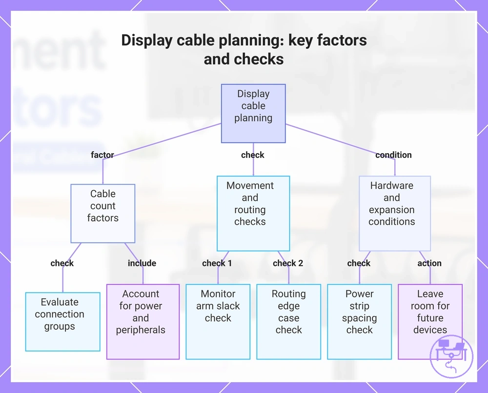
What affects cable count during display cable planning?
Cable count depends on the monitor layout, device connections, and whether a docking station is part of the setup. Cable count often increases when power cables, display cables, peripherals, and charging connections share the same workspace. The planning implication is to evaluate connection groups before organizing cable routes.
Can monitor arms change cable planning requirements?
Monitor arms can change cable planning when movement affects slack, routing, or access. Monitor arm movement may shift cable position and affect how easily connections remain reachable. The planning implication is to check cable movement before finalizing the cable path.
Should power strips be considered before choosing tray size?
Power strips should be considered when adapters and plugs occupy tray space. Adapter spacing and power strip placement can influence tray size, fit, and access. The planning implication is to account for both cables and power accessories together.
Does a sleeve solve routing edge cases?
A sleeve can help when a visible bundle needs grouping, but routing edge cases may still depend on cable path, access needs, and movement. Sleeves manage visible cable grouping rather than every routing condition. The planning implication is to treat sleeves as one part of connection planning.
How should tray size be evaluated when cable count changes?
Tray size should reflect expected cable growth when future devices or displays may be added. Cable count can change when monitors, chargers, or a docking station are added later. The planning implication is to leave room for reasonable expansion.
Can a docking station simplify display connection questions?
A docking station can simplify planning when multiple device connections become centralized. The total cable count may remain similar, but connection points are often concentrated in one area. The planning implication is to check access around the docking station location.
What should be checked in routing edge cases?
Routing edge cases should be checked when desk movement, wall clearance, or cable path restrictions affect access. Limited rear clearance and movement can make cable planning more sensitive to slack and positioning. The planning implication is to verify cable movement across the relevant desk layout.
This chart shows the main factors affecting cable count, the movement and routing checks, and the hardware and expansion conditions to consider during display cable planning.